18
MECHANICAL ADJUSTMENT
NEEDLE BAR HEIGHT
TO CHECk:
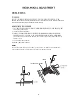
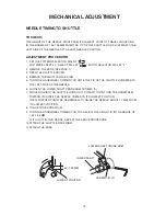
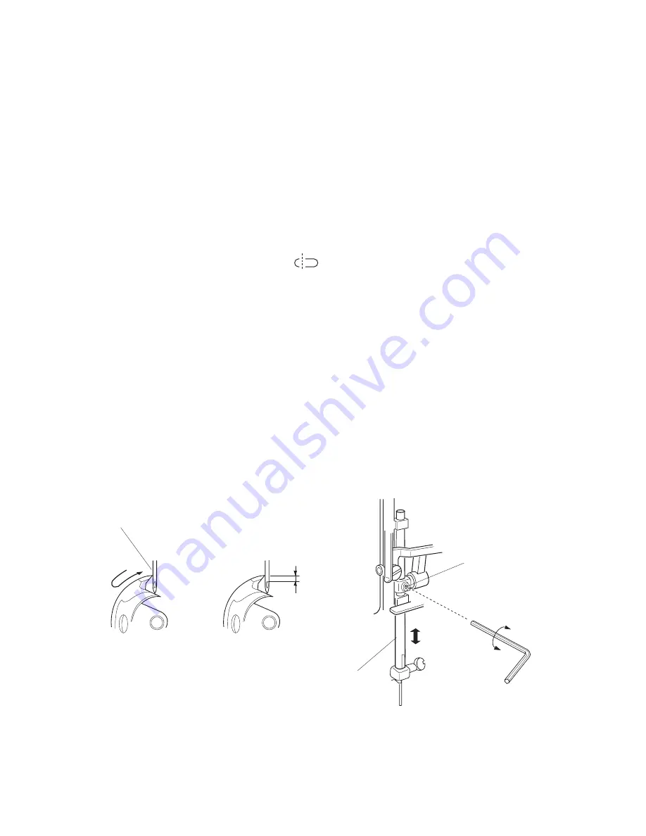
whEn thE tip of ShuttlE hook mEEtS thE lEft SidE of thE nEEdlE in aScEnding travEl
of thE nEEdlE from itS lEft and lowESt poSition, thE diStancE BEtwEEn thE top of
thE nEEdlE EYE and thE tip of thE ShuttlE hook Should BE in thE rangE of 2.9-3.5 mm.
ADJUSTMENT PROCEDURE:
1. rEmovE thE facE covEr.
2. SEt thE pattErn SElEctor dial at " ".
3. opEn thE ShuttlE covEr.
4. rEmovE thE ShuttlE racE ring.
5. turn thE handwhEEl toward You until thE tip of thE ShuttlE hook mEEtS thE lEft
SidE of thE nEEdlE.
6. looSEn thE lowEr Shaft crank arm ScrEw (a).
7. adjuSt thE hEight of thE nEEdlE Bar BY moving thE nEEdlE Bar upward or
downward without turning it.
8. tightEn thE ScrEw (a).
9. attach thE ShuttlE racE ring.
ScrEw (a)
nEEdlE Bar
tip of ShuttlE hook mEEtS
lEft SidE of nEEdlE
2.9–3.5 mm
Summary of Contents for NH15
Page 1: ...1 SERVICE MANUAL MODEL NH15 PARTS LIST...
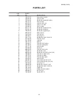
Page 23: ...23 WIRING 1 WIRING FOR MACHINE SOCKET UNIT L M M MOTOR L LAMP M L 120V 240V...
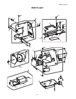
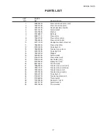
Page 34: ...34 MODEL NH15 PARTS LIST 1 2 3 4 4 5 6 7 8 9 10 11 12 13 14 8 4 15 16 17 8 8 18 19...
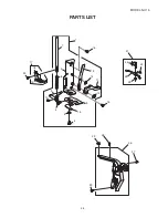
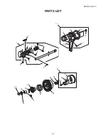
Page 38: ...38 MODEL NH15 PARTS LIST 1 2 3 9 5 8 6 7 4...
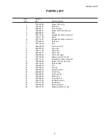
Page 40: ...40 MODEL NH15 PARTS LIST 2 8 1 4 5 7 6 3 9 10 11...

