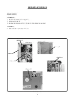
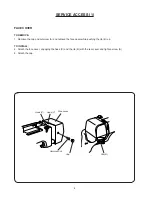
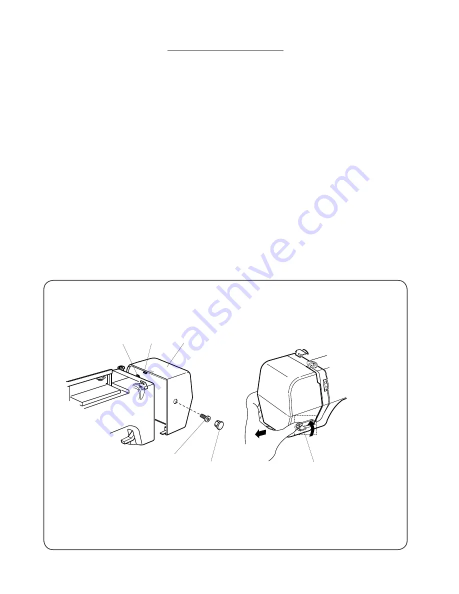
background image

4

SERVICE ACCESS (1)

FACE COVER


TO REMOVE:

1.  Remove the cap and setscrew (A) and remove the face cover while pushing the rib (B) up.

TO INSTALL:

2.  Attach the face cover, engaging the hook (C) and the rib (B) with the rear cover and tighten screw (A)
3.  Attach the cap.

Face cover

Setscrew (A)

Cap

Rib (B)

Hook (C)

Hook (C)

Summary of Contents for NH40

Page 1: ...SERVICE MANUAL MODEL NH40...

Page 2: ...12 Clearance between Needle and Hook Point 13 Backlash Lower Shaft Gear 14 Feed Dog Height 15 Needle Swing Timing 16 Needle Thread Tension 17 Stretch Stitch Feed Balance 18 Adjust the Buttonhole Lever...

Page 3: ...HA x 11 blue tip needle Adjust the presser bar level to make the pressure stronger See mechanical adjustment Needle bar height See mechanical adjustment Needle to hook timing See mechanical adjustment...

Page 4: ...ch thread is wound on the bobbin 3 Lint is stuck inside the bobbin holder 4 Thread quality is too low 5 Thread is jamming around the bobbin holder Set the bobbin thread correctly Adjust the position o...

Page 5: ...backlash lower shaft gear Eliminate the looseness See part removal and replacement driving motor DC motor Oil all moving parts P 14 P 27 P 31 7 Deformation pattern 1 Inappropriate feed balance 2 Inapp...

Page 6: ...the cap and setscrew A and remove the face cover while pushing the rib B up TO INSTALL 2 Attach the face cover engaging the hook C and the rib B with the rear cover and tighten screw A 3 Attach the c...

Page 7: ...5 BED COVER TO REMOVE 1 Remove the 4 setscrews A remove the bed cover TO INSTALL 2 Follow the above procedures in reverse SERVICE ACCESS 2 Setscrew A Setscrew A Setscrew A Bed cover Setscrew A...

Page 8: ...O REMOVE 1 Remove the needle plate 2 Remove the bed cover see page 5 3 Loosen the setscrew A and B TO INSTALL 4 Follow the above procedures in reverse SERVICE ACCESS 3 Setscrew A Setscrew B Free arm c...

Page 9: ...d loosen setscrew C 4 Disconnect all the connectors from the circuit board A see page 20 NOTE Do not disconnect the connectors by pulling on cord To disconnect grasp the connector not the cord Remove...

Page 10: ...E 1 Remove the front cover see pages 7 2 Loosen setscrews A 3 Remove the setscrews B C D and E then remove the rear cover TO INSTALL 4 Follow the above procedure in reverse Setscrew B Setscrew A Setsc...

Page 11: ...the foot and the feed dog window on the needle plate should be parallel 1 Remove the face cover see page 4 and raise the presser foot Loosen the setscrew to adjust the presser foot height 6 0 mm and t...

Page 12: ...s 1 Remove the face cover see page 4 2 Turn the power switch on and check the needle drop position 3 If the needle drop is out of position adjust it to proper position by turning the adjusting screw s...

Page 13: ...the pattern simple zigzag maximum zigzag width 3 Remove the bed cover see page 5 4 Turn the handwheel toward you and set the needle bar at the lowest position 5 Loosen the 2 setscrews on the lower sh...

Page 14: ...attern simple zigzag maximum zigzag width 4 Turn the handwheel toward you until the tip of hook meets the right side of the needle 5 Loosen the setscrew 6 Adjust the height of the needle bar by moving...

Page 15: ...B C then slightly tighten the hinge screw C 2 Turn the handwheel toward you to bring the hook point behind the needle Adjust the clearance between the test pin and the point of the hook in the left a...

Page 16: ...0 8 mm If there is more than 0 8 mm play adjust as follows ADJUSTMENT PROCEDURE 1 Remove the bed cover see page 5 and loosen the setscrew 2 Turn the lower shaft bushing eccentric in the direction A w...

Page 17: ...urn the power switch on 3 Select the straight stitch pattern with maximum length 4 Turn the handwheel toward you to set the feed dog at the highest position 5 Loosen the setscrew and nut 6 Adjust the...

Page 18: ...y with your hand until the needle start to swing Loosen the setscrew and turn the upper shaft shield plate in the direction of A If the swing point is higher than 8 7 mm B If the swing point is lower...

Page 19: ...ot within the above limit adjust as follows 1 Set the tension dial at 4 2 Lower the presser foot 3 Remove the front cover see page 7 4 Pull the spring D away from the lead screw If the top tension is...

Page 20: ...e Sew the stitch pattern 8 until the machine stop automatically and check the stitch length Standard length of five 8 characters 32 mm to 40 mm 4 Remove the base cap 5 If the length is too short turn...

Page 21: ...osition and open a 1 6 mm gap between the slider and the buttonhole foot 6 Turn the adjusting screw to the left until the LCD display BH symbol 7 Next turn the adjusting screw right until the BH symbo...

Page 22: ...ing on the cord To disconnect grasp the connector not the cord Connect the connector to the connector post of the same color on the circuit board Bobbin winder switch Upper shaft sensor Buttonhole sen...

Page 23: ...test you require by pressing the reverse button To begin Turn on the switch if any of the following problems occur take the recommended actions in the order they are shown 1 The machine does not respo...

Page 24: ...lever is pulled buzzer sounds and LCD displays BH symbol When the buttonhole lever is pushed buzzer sounds and LCD displays BH symbol LCD displays SC 04 When the bobbin winder spindle is moved to the...

Page 25: ...ce the circuit board A 06 Upper shaft positioning sensor 07 Zigzag motor Step motor Feed motor Turn the handwheel toward you Lower the needle bar from its highest to its lowest position Press the ring...

Page 26: ...board A 09 Not applicable for this model Press the ring button up mark If the result is correct condition press the reverse button to proceed the next step If the result is defective condition press t...

Page 27: ...determined Correct Buzzer sounds and LCD displays 00 Defective Caution buzzer sounds and LCD displays the defective part number Refer to page 22 24 and fix the defective part The defective part number...

Page 28: ...ot disconnect the connectors by pulling on cord To disconnect grasp the connector not the cord REPLACING PRINTED CIRCUIT BOARD A Setscrew Setscrew Setscrew Setscrew Setscrew Setscrew Circuit board A B...

Page 29: ...lt with 2 setscrews 4 Loosen the setscrews slightly and move the motor up or down to adjust the motor belt tension The belt should deflect 7 9 mm when applying 300 grams of load to the middle of the b...

Page 30: ...2 setscrews A and a setscrew B then remove the switching regulator TO INSTALL 3 Follow the above procedures in reverse NOTE Cords should not contact the lower shaft motor belt etc REPLACING SWITCHING...

Page 31: ...Remove 2 setscrews A 3 Remove E ring 4 Remove stepping motor zigzag TO INSTALL 5 Follow the above procedures in reverse NOTE Check the needle drop position after replacing the stepping motor REPLACING...

Page 32: ...setscrews A 3 Remove E ring 4 Remove stepping motor feed TO INSTALL 5 Follow the above procedures in reverse NOTE Check the stretch stitch balance after replacing the stepping motor REPLACING STEPPING...

Page 33: ...y parts need to be lubricated OIL Use good quality sewing machine oil at the points A B C D E F G H J K indicated by black arrows GREASE White grease is recommended for use on gears and cam surfaces I...

Reviews: