background image

1

Sew Mini

SERVICE ACCESS (1)

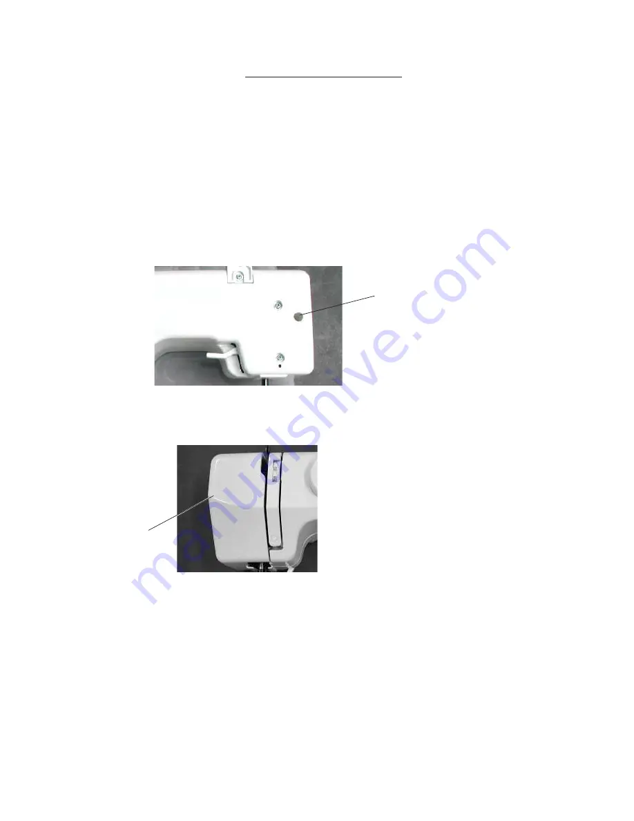
FACE COVER

1.  

Remove the face cover by removing the setscrew (A).

Face cover

(A)

Summary of Contents for SEW MINI DELUX

Page 1: ...SERVICE MANUAL SEW MINI DELUX...

Page 2: ...EEDLE DROP POSITION 4 ADJUSTING NEEDLE SWING 5 ADJUSTING NEEDLE TO HOOK TIMING 6 ADJUSTING CLEARANCE BETWEEN NEEDLE AND HOOK POINT 7 ADJUSTING NEEDLE BAR HEIGHT 8 ADJUSTING STITCH LENGTH 9 DISENGAGEME...

Page 3: ...1 Sew Mini SERVICE ACCESS 1 FACE COVER 1 Remove the face cover by removing the setscrew A Face cover A...

Page 4: ...emove the face cover 2 Pull out the dial and remove the set screws A E 3 Loosen the set screws F G 4 Remove the front cover NOTE Do not remove the set screws H TO ATTACH 5 Follow the above procedure i...

Page 5: ...urn the adjusting screw C in the direction of B when the upper thread tension is too loose 3 Attach the front cover and the face cover C C B A C TO CHECK The standard upper thread tension should be 75...

Page 6: ...in the center of the needle hole when the straight stitch is selected TO ADJUST 1 Remove the face cover 2 Select the straight stitch and the zigzag stitch 3 Loosen the setscrew A and adjust the needle...

Page 7: ...needle swing starts at 1 2mm above the needle plate after the needle has come out of the right side of the needle hole 5 Tighten two setscrews 6 Mount the front cover ADJUSTING NEEDLE SWING TO CHECK...

Page 8: ...o the right lowest position 5 Loosen the 2 setscrews C on the lower shaft gear 6 Raise the needle 2 0mm from the lowest position 7 While holding the handwheel as not to move the needle bar rotate the...

Page 9: ...st the clearance by turning the screw F in and out 5 Tighten 2 setscrews C 6 Check the clearance in the right and left needle positions 7 Attach the bobbin holder needle plate and presser foot The sta...

Page 10: ...le to hook timing 1 Select the maximum width zigzag stitch 2 Remove the presser foot needle plate A and bobbin holder B 3 Turn the handwheel toward you until the hook point meets the right side of the...

Page 11: ...should be 3 0mm 1 Set the pattern selector dial at maximum stitch length 2 If the stitch length is longer than 3 0mm turn the adjusting screw in the direction A If the stitch length is shorter than 3...

Page 12: ...you and put the cam follower to the zigzag cam 4 Loosen the setscrew 5 Move adjusting plate in the direction of arrow until to touch to the releasing arm and tighten set screw NOTE After this adjustme...

Page 13: ...en the deflection of motor belt is about 7mm 9mm When pushing the motor belt by finger with a 100 gram load TO ADJUST 1 Remove the face cover and front cover 2 Loosen the setscrews A and B and adjust...

Page 14: ...positions of the parts on the lower shaft are as shown below The setting angle of the upper shaft bevel gear setscrew A lower shaft bevel gear setscrew B and the feed cam C setting mark should be at t...

Reviews: