background image

3

Sew Mini

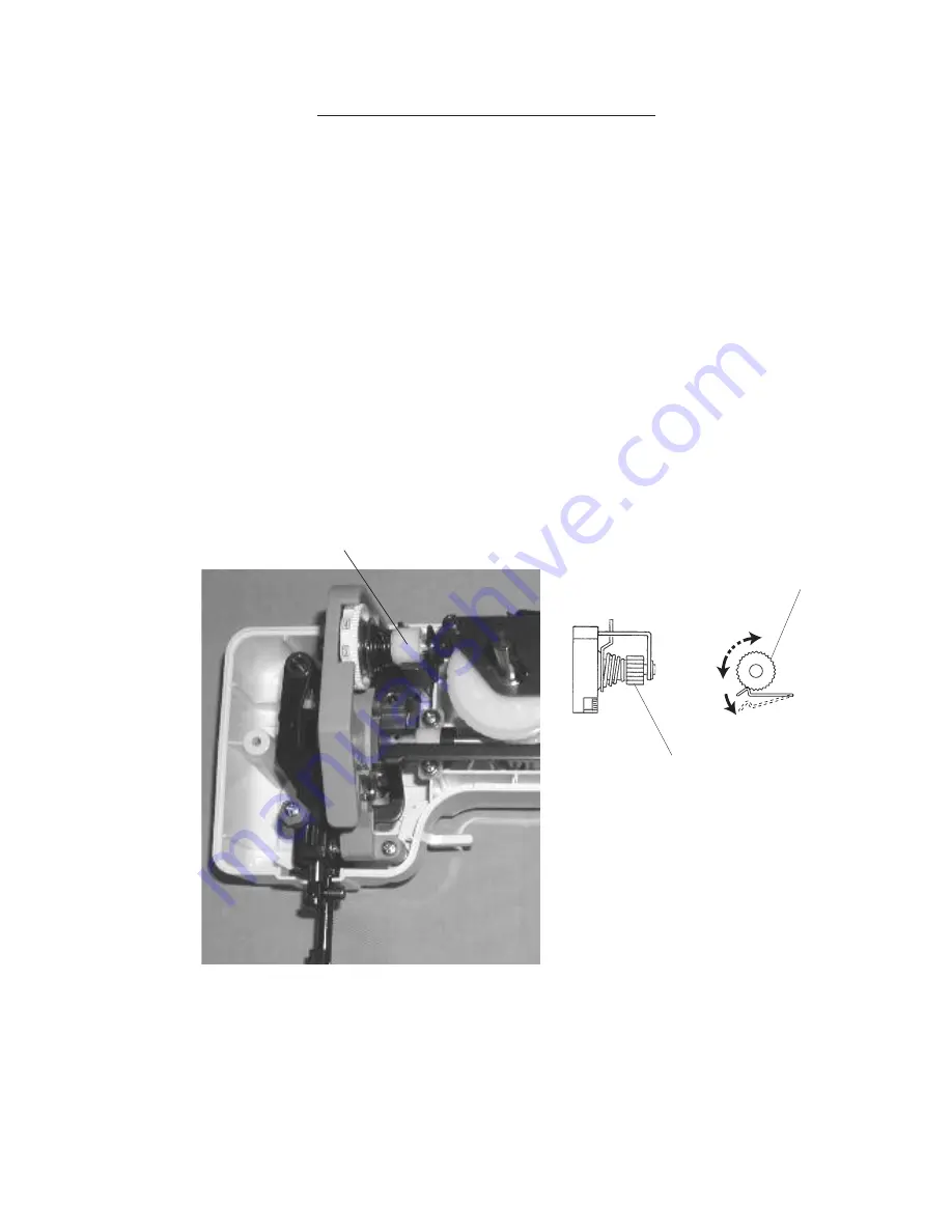
ADJUSTING THREAD TENSION

TO ADJUST
1.  Remove the face cover and the front cover.
2.  Turn the adjusting screw (C) in the direction of (A) when the upper thread tension is too  
  tight.
  Turn the adjusting screw (C) in the direction of (B) when the upper thread tension is too  
  loose.
3.  Attach the front cover and the face cover.

(C)

(C)

(B)

(A)

(C)


TO CHECK

The standard upper thread tension should be 75 - 90g when pulling the thread (polyester 
thread #50) with setting the tension dial at “4”. 
(Make sure the foot should be lowered.)
If the tension is out of the standard range, adjust it as follows: 

Summary of Contents for SEW MINI DELUX

Page 1: ...SERVICE MANUAL SEW MINI DELUX...

Page 2: ...EEDLE DROP POSITION 4 ADJUSTING NEEDLE SWING 5 ADJUSTING NEEDLE TO HOOK TIMING 6 ADJUSTING CLEARANCE BETWEEN NEEDLE AND HOOK POINT 7 ADJUSTING NEEDLE BAR HEIGHT 8 ADJUSTING STITCH LENGTH 9 DISENGAGEME...

Page 3: ...1 Sew Mini SERVICE ACCESS 1 FACE COVER 1 Remove the face cover by removing the setscrew A Face cover A...

Page 4: ...emove the face cover 2 Pull out the dial and remove the set screws A E 3 Loosen the set screws F G 4 Remove the front cover NOTE Do not remove the set screws H TO ATTACH 5 Follow the above procedure i...

Page 5: ...urn the adjusting screw C in the direction of B when the upper thread tension is too loose 3 Attach the front cover and the face cover C C B A C TO CHECK The standard upper thread tension should be 75...

Page 6: ...in the center of the needle hole when the straight stitch is selected TO ADJUST 1 Remove the face cover 2 Select the straight stitch and the zigzag stitch 3 Loosen the setscrew A and adjust the needle...

Page 7: ...needle swing starts at 1 2mm above the needle plate after the needle has come out of the right side of the needle hole 5 Tighten two setscrews 6 Mount the front cover ADJUSTING NEEDLE SWING TO CHECK...

Page 8: ...o the right lowest position 5 Loosen the 2 setscrews C on the lower shaft gear 6 Raise the needle 2 0mm from the lowest position 7 While holding the handwheel as not to move the needle bar rotate the...

Page 9: ...st the clearance by turning the screw F in and out 5 Tighten 2 setscrews C 6 Check the clearance in the right and left needle positions 7 Attach the bobbin holder needle plate and presser foot The sta...

Page 10: ...le to hook timing 1 Select the maximum width zigzag stitch 2 Remove the presser foot needle plate A and bobbin holder B 3 Turn the handwheel toward you until the hook point meets the right side of the...

Page 11: ...should be 3 0mm 1 Set the pattern selector dial at maximum stitch length 2 If the stitch length is longer than 3 0mm turn the adjusting screw in the direction A If the stitch length is shorter than 3...

Page 12: ...you and put the cam follower to the zigzag cam 4 Loosen the setscrew 5 Move adjusting plate in the direction of arrow until to touch to the releasing arm and tighten set screw NOTE After this adjustme...

Page 13: ...en the deflection of motor belt is about 7mm 9mm When pushing the motor belt by finger with a 100 gram load TO ADJUST 1 Remove the face cover and front cover 2 Loosen the setscrews A and B and adjust...

Page 14: ...positions of the parts on the lower shaft are as shown below The setting angle of the upper shaft bevel gear setscrew A lower shaft bevel gear setscrew B and the feed cam C setting mark should be at t...

Reviews: