
21
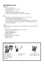
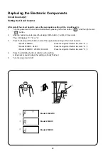
Correct Condition
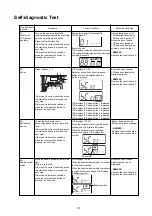
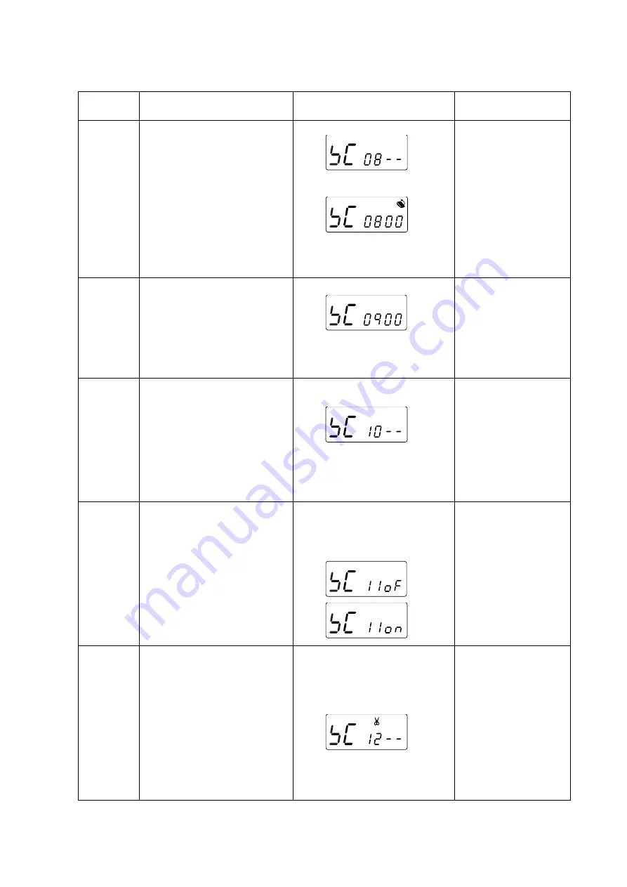
LCD displays “SC 08”.
Step and
items to check
08)
Foot control
Procedure
Attach the foot control to the sewing
machine.
Depress the foot control as far as it
goes, then release it.
If the result is correct condition, press
the start/stop button to proceed the
next step.
If the result is defective condition,
press the reverse stitch button to
proceed the next step.
Defective Condition
The foot control symbol does
not appear.
Buzzer does not sound.
–REMEDY–
Replace the foot control.
Replace the machine socket.
Replace the circuit board A.
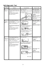
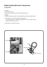
Shift the slide volume from left to right,
then return to the left.
If the result is correct condition, press
the start/stop button to proceed the
next step.
If the result is defective condition,
press the reverse stitch button to
proceed the next step.
09)
Slide volume
Press the needle up/down button.
If the result is correct condition, press
the start/stop button to proceed the
next step.
If the result is defective condition,
press the reverse stitch button to
proceed the next step.
The foot control symbol appears when
the foot control is attached.
Buzzer sounds when the foot control is
deeply depressed.
Buzzer sounds when the foot control is
relased.
LCD displays “SC 09”.
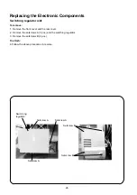
10)
DC motor
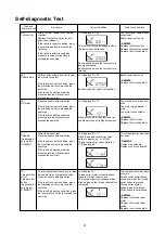
11)
Solenoid
(Applicable for
only model
3160QDC)
12)
Thread cutter
motor,
Thread cutter
button
(Applicable for
only model
3160QDC)
Buzzer sounds at right or left position.
LCD displays “SC 10”.
Machine runs slow, then fast, and the
needle bar stops at its highest position.
LCD displays “SC 11”.
Press the needle up/down position
button to display “on” or “of”(off).
Thread tension disc opens while the
LCD displays “on”.
LCD display “12”.
Thread cutter motor wii be initialized.
Press the thread cutter button.
The thread cutter icon will appear and
blink as long as the thread cutter button
is pressed.
Lower the presser foot.
Press the needle up/down button.
If the result is correct condition, press
the start/stop button to proceed the
next step.
If the result is defective condition,
press the reverse stitch button to
proceed the next step.
Buzzer does not sound.
–REMEDY–
Replace the circuit board A.
The machine motor does not
start.
The motor stops immedi-
ately.
The motor runs unstable.
–REMEDY–
Replace the DC motor.
Replace the circuit board A.
Turn the handwheel toward you to raise
the needle bar at its highest position.
Press the needle up/down button.
If the result is correct condition, press
the start/stop button to proceed the
next step.
If the result is defective condition, press
the reverse stitch button to proceed the
next step.
The thread tension disc does
not open.
–REMEDY–
Replace the solenoid
Replace the circuit board A.
The thread cutter motor does
not work.
Thread cutter symbol does
not appear when the thread
cutter button is pressed.
Thread cutter symbol
appears when the thread
cutter button is not pressed.
–REMEDY–
Replace the thread cutter
motor.
Replace the thread cutter
switch.
Replace the circuit board A.
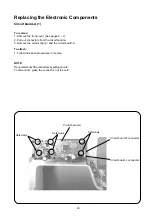
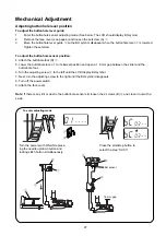
Self-diagnostic Test


