
43
2030DC
XL6001
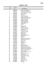
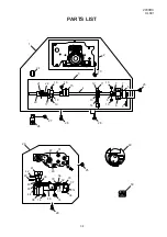
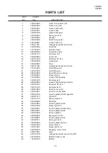
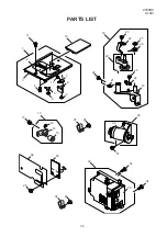
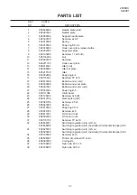
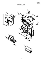
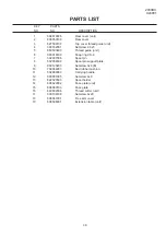
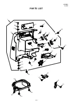
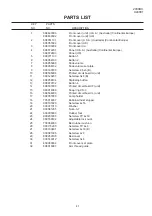
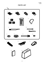
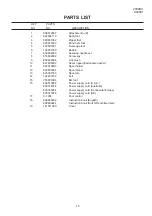
PARTS LIST
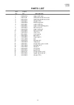
KEY
PARTS
NO.
NO.
DESCRIPTION
1
2
3
4
5
6
7
8
9
10
11
12
13
14
15
16
17
18
19
808870007
822804118
829801002
825817009
822801001
102261000
639804000
653802002
802424004
647808009
822019509
829803004
625031500
102403109
753801004
856519004
830314018
830335004
830377008
C-1036
808800202
808800224
741811000
Attachment (unit)
Satin foot
Zipper foot
Blind hem foot
Overedge foot
Bobbin
Assorted needle set
Screw key
Lint brush
Seam ripper (Buttonhole opener)
Spool holder
Spool stand
Spool pin
Felt
BH foot
Power supply cord (U.S.A.)
Power supply cord (Australia)
Power supply cord (Continental Europe)
Power supply cord (UK)
Foot control
Instruction book (English)
Instruction book (Dutch/French/German)
Cover


