

REGIS F – Access or time and attendance controller with integrated fingerprint reader
9/2016
Black line
www.jantar.si
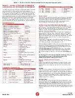
REGIS F – ACCESS or TIME AND ATTENDANCE
CONTROLLER with INTEGRATED FINGERPRINT
The Regis is a controller with built-in fingerprint reader, proximity
card reader and 3” LCD capacitive touch screen display. It is
designed for residential and business buildings, offices, shops, etc.
The controller can have 125kHz or 13.56MHz reading frequency.
The entire set-up procedure is carried out with the software. The
controller allows access for up to 500 fingerprints, 30000 users and
saves 100000 events. If you bought the controller in time and
attendance KIT, then inputs and outputs cannot be controlled.
The SDK is also available for this controller. If a user or software
producer wants to develop its own application, please contact us.
TECHNICAL DATA
REGIS F
REGIS F-1-B reading frequency
125kHz
REGIS F-1-B reading distance
Up to 10cm
REGIS F-1-9 current consumption in
standby mode
200mA
REGIS F-3-B reading frequency
13.56MHz
REGIS F-3-B reading distance
Up to 7cm
REGIS F-3-B current consumption in
standby mode
230mA
Dimensions (mm)
(WxHxD)
Protection
IP21
Operating voltage
From 9V to 14V DC
Operating temperature
From -20°C to 60°C
Display
3”
TFT - resistive touch
Tamper
Accelerometer
Display resolution
400 x
240
Humidity
10-80%, non condensing
Memory
500 finger prints
30000 cards or codes
100000 events
Inputs
Door status
Push button
Outputs
Transistor output for el. strike
0.5A
Clock
Real time clock, battery backup
(max. ten hours)
Communication
RS485
Ethernet
Keypad
Configurable buttons and
selectable colors – with Keypad
Editor
Sensor protection
> 15kV ESD protection
Sensor usage
> 1 million wear cycles
CONNECTOR DESCRIPTION
Contact
Description
Specification
1 - UIN
9-14V DC
Power supply
2 - GND
GND
Ground
3 - CA
CA - RS485
Communication line
4 - CB
CB - RS485
Communication line
5 - O0
El. strike output
Max. 0,5A
When active = GND
6 - O1
Alarm output
When active = GND
7 - I0
Door status switch input
Active when
connected to GND
8 - I1
Push button input
Active when
connected to GND
ETHERNET
Contact
Description
Specification
RJ45 connector
9 - TXP
Ethernet
TXP
1 – white/orange
10 - TXN
Ethernet
TXN
2 – orange
11 - RXP
Ethernet
RXP
3 – white/green
12 - RXN
Ethernet
RXN
6 - green
Power supply
The controller need’s external power supply to operate. The Spider
W40 power supply is sufficient to power two controllers and two
12V electric strikes or two 12V magnetic locks (0.5A). If you will
use it as a standalone controller and low consumption electric
strike (0.25A) you can use power supply Spider W5.
Voltage drops and cable signal interferences
When you connect the controller, use cable with a diameter of at
least 0.22mm
2
. If the cable length exceeds 25m, use one twisted
pair of UTP cables for the positive (+) pole and one for the
negative (-) pole. The cable length between power supply and the
controller should not exceed 50m.
Take into consideration that a 0.22mm
2
cable has a resistance of
approximately 9 ohm per 100m. The power supply at the end of
cable should be a minimum of 9V. If you are using el. strike, it is
highly recommended that the voltage drop is calculated. At greater
distances, a thicker cable of 0.5mm
2
or more should be used
wherever possible.
If the load is, for example, 0.5A (with el. strike) then, on the
0.22mm
2
cable voltage drop will be 4.5V at 100m. For the device
with 60mA consumption, the voltage drop is 0.5V.
Reading distance depends on where the controller is installed. The
presence of metal or interferences can significantly reduce the
reading distance.
DO NOT
install the controller directly on metal
surfaces and/or cover it with a metal cover.
It is
not recommended
to install controllers closer than
30cm
from each other in any direction. Otherwise, it may result in
inaccurate readings or, indeed, in the controller
not reading at
all
.
For the Regis F-3-B to comply with EMC directives (CE), you
have to put ferrite core on the cable as close to the
controller as possible, making two turns!
Inputs, outputs and environment
Inputs:
Inputs are realized with opto-isolators. The input is active, when
pulled to ground with an open collector transistor or mechanical
switch, which is connecting the input pin of the controller to the
Ground.
Outputs:
Output has a pre-installed protection diode for an inductive load. It
is also protected from current overload. The best way is to use a
0.25A el. strike or a 0.5A el. magnet, which has to be connected to
the same positive pole (+) as the controller. Connect the negative
pole (-) to the door strike output (wire 3). When the output is
active it is pulled to ground. This can be changed with function 5 –
negate output (for el. magnet).
Reading range:
The controller has a program algorithm that, at power start, sets
parameters based on the installation environment, so as to ensure
an optimal reading range.
DO NOT
install the controller directly on
metal surfaces and/or cover it with a metal cover; it may stop
working/reading. If you plan to test the controller and move it onto
different surfaces, then you have to reset it (power off/on) on each
surface.


