LTE910CF Plug-In Hardware User Manual JA03-UM-LTE-Cat1 Page 8 Rev: P01 Date: 04/04/18
© Copyright 2018 Janus Remote Communications
Specifications subject to change without notice
All Rights Reserved See website for latest revision. Not intended for life support applications.
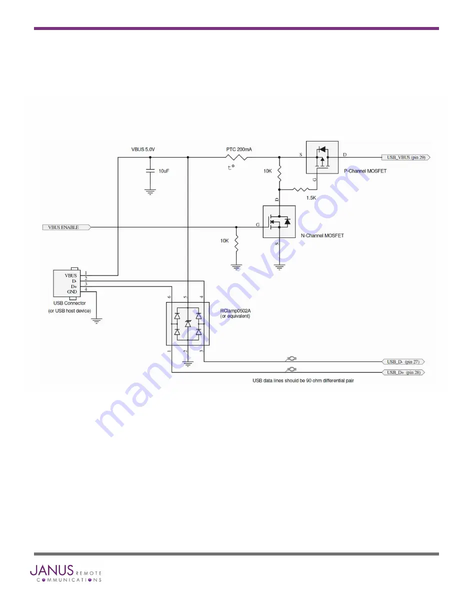
Figure 3 USB Connection Diagram
4 Interfaces continued
4.2.2 USB Port continued
4.2.2.1 USB Connection Diagram
When VBUS_ENABLE is HIGH the VBUS 5.0v signal will be passed to USB_VBUS, (pin 29) turning the USB ON.


