


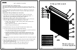


A rolling door is a large heavy object that moves
with the help of springs under extreme tension and
follow these instructions.
electric motors. Moving objects and springs under
tension and electric motors can cause serious injuries
or death. For your safety and the safety of others,
WARNING!
Use proper lifting equipment and correct
lifting procedures to avoid damage or injury.
CAUTION
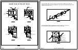
SAFETY INFORMATION
POTENTIAL HAZARD
EFFECT
PREVENTION
MOVING DOOR
ELECTRICAL SHOCK
HIGH SPRING TENSION
WARNING
Could result in death
or serious injury
Keep people clear of opening while Door is moving.
DO NOT allow children to play with the Door Operator.
DO NOT operate a Door that jams or one that has a broken spring.
Turn off power before removing operator cover.
When replacing operator cover, make sure wires are not pinched or near
moving parts.
Operator must be properly grounded.
DO NOT try to remove, repair or adjust springs or anything to which Door
spring parts are fastened, such as steel brackets or other like items.
Repairs and adjustments must be made by a trained door system
technician using proper tools and instructions.
OVERVIEW OF POTENTIAL HAZARDS
WARNING
Could result in death
or serious injury
WARNING
Could result in death
or serious injury
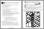
Overhead doors are large, heavy objects that move with the help of springs under high tension and electric motors. Since
moving objects, springs under tension, and electric motors can cause injuries, your safety and the safety of others depend
on you reading the information in this manual. If you have questions or do not understand the information presented, call
your nearest service representative.
In this section, and those that follow, the words "Danger", "Warning", and "Caution" are used to emphasize important safety
information. For example:
if not avoided, may result in injury or property damage.
which, if not avoided, could result in death
if not avoided, will result in death or serious injury.
or serious inury.
Door must be fully opened when making adjustments.
Repairs and adjustments must be made by a trained rolling door systems
technician using proper tools and instructions.
WARNING
Could result in death
or serious injury
PAGE 1
ASTA DOOR CORPORATION
DANGER:
Indicates an imminently hazardous situation which,
WARNING:
Indicates a potentially hazardous situation
CAUTION:
Indicates a potentially hazardous situation which,
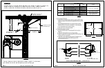
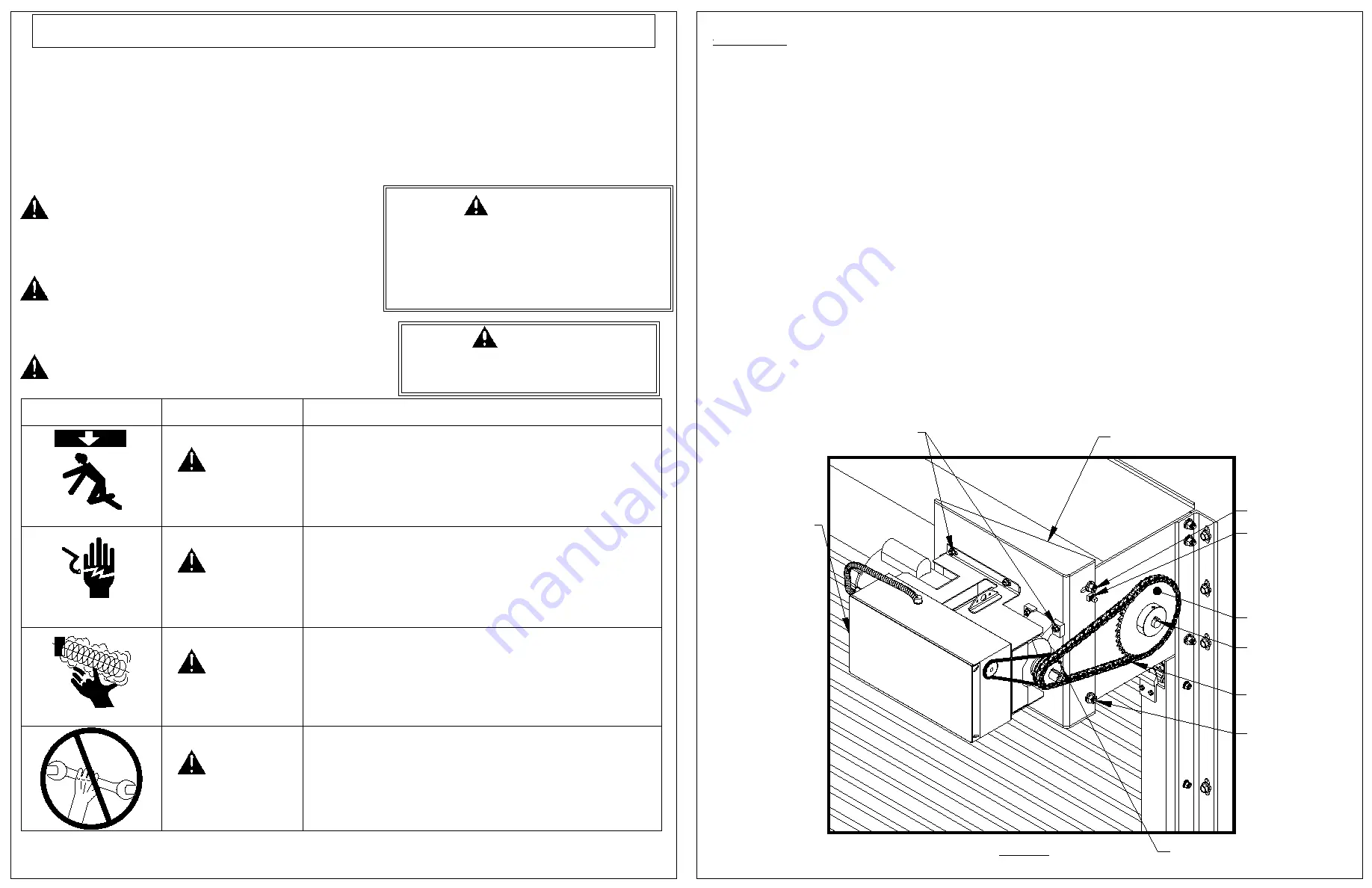
FIGURE C-1
PAGE C-1
ASTA DOOR CORPORATION
Appendix "C"
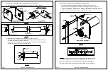
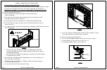
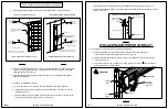
1. Verify the barrel and guide assemblies are properly installed and that all
fasteners are tightened securely.
2. Procedure for installation of motor operator.
a. Attach the operator to bracket using the supplied hex bolts,
flat washers, lock washers and hex nuts as shown in Figure C-1.
b. Install motor operator and bracket assembly to the drive side headplate
with two 1/2" -13 NC X 1 1/4" carriage bolts as shown in Figure C-1.
c. Push the assembly toward wall as far as possible for drive chain
installation, and temporarily secure the two carriage bolts as shown in
Figure C-1.
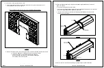
d. Install the drive shaft sprocket with supplied key way.
e. Align the drive shaft and operator sprockets and tighten set screws.
f. Size & install the supplied #50 roller chain and secure with #50 master link.
g. Loosen the operator carriage bolts and tighten the roller chain by pulling
the assembly away from the wall leaving approximately 3/4" slack in chain.
h. Tighten operator bracket carriage bolts and set screw to lock the bracket
in place and to retain roller chain setting during future operation.
MOTOR OPERATOR
OPERATOR BRACKET
SET SCREW
1/2" CARRIAGE BOLT
PIVOT BOLT
OPERATOR FASTENERS
KEY WAY
DRIVE SPROCKET
OPERATOR SPROCKET
#50 ROLLER CHAIN
ASTA Door Corporation 500 Series FIRE DOOR
Motor Operator Installation


