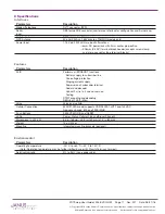
POTSwap User Guide JA16-EVDO-UM
Page 13 Rev: P07 Date: 08/01/16
© Copyright 2016 Janus Remote Communications
Specifications subject to change without notice
All Rights Reserved See website for latest revision. Not intended for life support applications.
5 External Interfaces continued
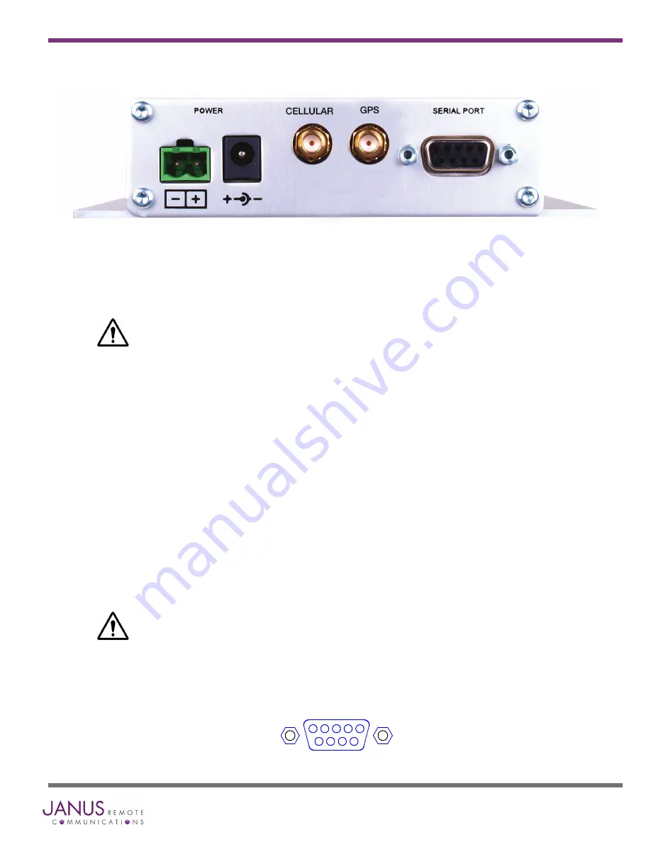
5.2 Rear Panel
Figure 6 Rear Panel
Figure 7 Serial Port
Power connectors:
Two types of power connector are provided on the POTSwap. These two connectors are connected directly
together internally, and are simply provided as a user convenience.
DO NOT APPLY POWER TO BOTH CONNECTORS SIMULTANEOUSLY
The negative terminal of the power supply is connected to the enclosure.
Power supply range can be found in the Specifications section.
Terminal Block Header: This is an industry standard 5.08 mm header that accepts a variety of terminal blocks,
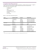
including screw terminal, spring clamp and crimp terminal type. See Section 9 – Compatible Terminal Block
Connectors.
Circular Jack: The circular DC jack has a 6 mm hole diameter and a 2 mm center pin. It is designed to accept
a 5.5 mm diameter plug with a 2.1 mm center hole and a 8.5 mm barrel length. The center pin is the positive
terminal.
Antenna Connectors:
CELLULAR: A standard 50 ohm SMA connector is provided for connecting a cellular antenna. The placement of
the antenna affects connectivity; a remote antenna location may be necessary in some situations.
GPS: A standard 50 ohm SMA connector is provided for connecting a GPS antenna. The GPS connector is
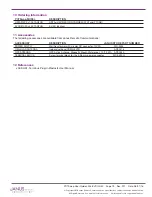
available on the EVDO910PS ‘TAGFNG’ version, and requires firmware version 160714 to operate. See section
7 - GPS.
The GPS connector provides a 2.85V bias voltage for active antennas.
Serial Port:
The female DB9 connector is configured as DCE (Data Communications Equipment) and provides a data path for
user configuration, firmware uploads and debug support.
5 4 3 2 1
6
7
8
9


