background image

01ETM

ISO 9001, ISO 14001 Certified

Printed in Japan

Marine Service Department

+81-3-3492-1305
+81-3-3779-1420
tmsc@jrc.co.jp

Telephone :
Facsimile :
e-mail :

AMSTERDAM Branch

Telephone :
Facsimile :
e-mail :

+31-20-658-0750
+31-20-658-0755
service@jrcams.nl

SEATTLE Branch

Telephone :
Facsimile :
e-mail :

+1-206-654-5644
+1-206-654-7030
service@jrcamerica.com

CODE No.7ZPNA2002

CODE No.7ZPNA2002

APR. 2007  Edition 1      JRC

APR. 2007  Edition 1      JRC

Not use the asbestos 

For further information,contact:

URL

http://www.jrc.co.jp

INSTRUCTION

INSTRUCTION

MANUAL

MANUAL

Echo Sounder

Echo Sounder

JFE-380

JFE-380

Summary of Contents for JFE-380

Page 1: ...e mail 31 20 658 0750 31 20 658 0755 service jrcams nl SEATTLE Branch Telephone Facsimile e mail 1 206 654 5644 1 206 654 7030 service jrcamerica com CODE No 7ZPNA2002 CODE No 7ZPNA2002 APR 2007 Editi...

Page 2: ...4th edition...

Page 3: ...isplays Before attempting to operate this equipment read this instruction manual thoroughly to ensure correct and safe operation in accordance with the warning instructions and operation procedures Yo...

Page 4: ...General Information ii 4th edition...

Page 5: ...ncorrect handling may result in injury to the operator or physical damage to the equipment Example Pictograms This mark is intended to alert the user to the presence of precautions including danger an...

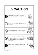
Page 6: ...g may result in fire electric shock or damage Do not place any vessels containing water or other liquids or metal objects on top of this equipment If water is spilled on or metal objects fall into the...

Page 7: ...tely turn off the power switch then contact JRC or its agent There is a risk of file or electric shock if you continue to use the equipment If you notice smoke unusual smells or abnormal heat coming f...

Page 8: ...bserve this condition may result in the equipment falling or toppling over resulting in injury If it is cold do not move the equipment suddenly into a warm environment and switch it on High voltage le...

Page 9: ...damaged resulting in a fire or an electrical shock Do not install the units on the place being poor ventilation Otherwise the set that is heated may cause a fire or failure For safety when the equipm...

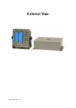
Page 10: ...External View External View viii...

Page 11: ...andard mode 4 2 History mode 4 3 Docking mode 5 Operation 5 1 Basic Operations 5 2 Menu Operations 5 3 Master Reset 6 Replacing the Fuses 7 Consider Installation 8 Troubleshooting 9 After sales Servic...

Page 12: ...unifies format approval standards implemented separately by each European NMEA0183 NMEA stands for the National Marine Electronics Association NMEA0183 is the format used when sending or receiving de...

Page 13: ...epth data for last 24 hours in memory to play back the past sounding information Dual frequency mode and two transducers are available in option requires an optional equipment Conforms to the IMO Stan...

Page 14: ...9133 1 10m Matching box primary AW 154F 1 200kHz transducer mounting primary NKF 341 1 200kHz with cable 20 30 40m AW 154F 1 200kHz Matching box secondary AW 154F 50 1 50kHz NKF 341 1 200kHz with cabl...

Page 15: ...1 4 Construction Equipment Outline The following shows the external dimensions of the JFE 380 1 External Dimension of JFE 380 2 Dimensions of AW 154F 50 AW 154F 50 Matching box 1 Introduction 3...

Page 16: ...nal dimensions illustrated below are for the standard equipment Please refer to the separately supplied drawings if your specifications are not standard 1 NKF 341 NKF 345 Installed on ship s bottom 2...

Page 17: ...1 5 System Configuration 1 Introduction 5...

Page 18: ...he equipment on unstable or unlevel surfaces Failure to observe this condition may result in the equipment falling or toppling over resulting in injury Take care when laying the transducer cable power...

Page 19: ...2 1 Installing the Recorder Unit Flush Mounted Equipment Figure 3 1 2 Installation 7...

Page 20: ...Wall Mounted Equipment Figure 3 2 2 Installation 8...

Page 21: ...alling the Transducer The external dimensions illustrated below are for the standard equipment Please refer to the separately supplied drawings if your specifications are not standard NKF 341 2 Instal...

Page 22: ...NKF 345 2 Installation 10...

Page 23: ...NKF 392C 2 Installation 11...

Page 24: ...ached to the connectors and must not contact any other connectors etc 2 Casings must be grounded securely to the ship s hull using copper plates 3 The exterior is to be grounded to the ship s hull cab...

Page 25: ...DE Switches the display modes 6 CLR Clears an item 7 RANGE Switches the depth range to shallow or deep 8 GAIN Adjusts the sensitivity high or low 9 DAY NIGHT Enhances the visibility of the screen 10 P...

Page 26: ...4 Display 4 1 Standard mode dual frequency 4 Display 14...

Page 27: ...4 2 History mode 4 Display 15 Keel height value...

Page 28: ...4 3 Docking mode 4 Display 16...

Page 29: ...ss the PWR PANEL key and use the arrow keys to adjust the control panel brightness The control panel illumination can not be turned fully off it can only be dimmed Adjusting Screen Brilliance BRILL Th...

Page 30: ...uring range 2 You must display the seabed otherwise you don t see the depth value Automatic Range In the Automatic range mode the range scale is automatically adjusted Turn on the power or press and h...

Page 31: ...by monitoring the image being plotted on the screen See figure below Increase sensitivity Good Decrease sensitivity Automatic Gain In the Automatic gain mode the sensitivity is automatically adjusted...

Page 32: ...ngle frequency standard mode primary Single frequency standard mode secondary Dual frequency standard mode Single frequency history mode primary Single frequency history mode secondary Docking mode Ad...

Page 33: ...Menu Tree 1 5 Operation 21...

Page 34: ...Menu Tree 2 5 Operation 22...

Page 35: ...ys to select the item to be changed The selected item is highlighted on the display In the figure at above DISPLAY is selected When an item is highlighted press the ENT key to change the setting Switc...

Page 36: ...mpares it with the last two data IR3 compares it with the last three data Gain Choose manual or automatic Range Choose manual or automatic Draft Enter the desired value The draft can be set between 0...

Page 37: ...ich alarm is being issued from the blinking characters 2 If due to bubbling etc it is not possible to discriminate the sea bottom it is also not possible to trigger the depth alarm When sailing in sha...

Page 38: ...displays the depth below water surface TRAN displays the depth below the transducer KEEL displays the depth below the keel see figure A Primary Enter the data of the primary transducer frequency posit...

Page 39: ...print Print mode COPY prints the data displayed on the present screen HISTORY prints all the saved data graphically LOG prints a specific period of the saved data see figure C for example Log length...

Page 40: ...ing values 3 Measuring range RANGE in meters only 4 Checksum result after each ASCII code of every character between S just after and X just before is EXORed 3 In the case of NMEA0183V1 5 the output s...

Page 41: ...1 primary depth alarm 352 secondary depth alarm 353 primary depth lost 354 secondary depth lost 356 recording paper is not good 357 printer connection is not good 360 primary output data is not good 3...

Page 42: ...Signal PRINTER PORT OUT PRINTER PC Display the window shown above The mode switches each time you press the up or downward arrow key When PRINTER is selected a printer control signal is output When PC...

Page 43: ...ansducer Controller is faulty and requires servicing See the list of offices at the end of this manual LCD Check SELF TEST CONTROL UNIT LCD UNIT KEY UNIT PRINTER TEST ALARM TEST Display the window sho...

Page 44: ...uire servicing See the list of offices at the end of this manual Printer Test SELF TEST CONTROL UNIT LCD UNIT KEY UNIT PRINTER TEST ALARM TEST Display the window shown above Use the up or downward arr...

Page 45: ...ter or the printer port by pressing the ENT key Alarm log deletion Deletes all the alarm log by pressing the ENT key Line monitor NAV DEPTH displays the Input output data of navigation and depth by pr...

Page 46: ...tting the equipment to the standard defaults the frequency setting menu window which said please do connection setting of transducers appears on the screen You cannot abort this operation after the fr...

Page 47: ...n OFF the main power switch to the side marked O on the power supply CQD 2082 before replacing the fuses No Type No Spec Part Code Remarks F1 250V 1A TLC 5A 250V 1A 5ZFCA00147 F2 MF51NR 250V 0 5 250V...

Page 48: ...9132 CFQ 9131 CFQ 9130 CFQ 9125 the Display the Power Supply CBD 1810 or the Control Block CCK 962 may be faulty Contact JRC or its agent See the list of offices at the end of this manual 3 Replacing...

Page 49: ...failures and reduce the life of the equipment 1 Where liable to be splashed with water 2 Where ventilation is poor Do not coat the part of the transducer that outputs the ultrasonic waves the rubber p...

Page 50: ...rong installation of the transducer Check the transducer No echo sounding picture Frequency setting is wrong Check the frequency setting Low sensitivity Increase the gain Muddy seabed Increase the gai...

Page 51: ...r will be made at your expense Details to be Submitted Name type No month and year of manufacture and serial number Nature of fault in as much detail as possible Contact details your name address and...

Page 52: ...10 Disposal 10 1 Disposal of this equipment Please dispose of this equipment following the guidelines of the local body governing the location at which the equipment is disposed of 10 Disposal 40...

Page 53: ...x IPX2 drip proof Input nav data IEC61162 1NMEA0183 RMA RMC GGA GLL VTG ZDA Input ACK signal IEC61162 1NMEA0183 ALR Input signals Power fail alarm ACK Contact input 12VDC 2 4mA current control 12VDC 1...

Page 54: ...Appendix Noise Bubble Noise Bubble Interruption Interference Noise from other ship Plankton layer Appendix 42...

Page 55: ...ucer or surface or sea but reflected at the hull bottom or surface of sea and again reflected at the seabed toward the transducer Such multiple recording of the seabed may appear due to change of bott...

Page 56: ...n right chart In case of a soft seabed made of mud seaweed etc they poorly reflect an ultrasonic wave to result in thin recording of the seabed with short trail The seabed quality can be more sufficie...

Page 57: ...bove the slope when recording In case of flat seabed thin second return of seabed may sometimes appear which is slightly below the actual seabed In either case the dim or thin echoes are false and pro...

Page 58: ...see and less discriminative since it tends to accompany with a false echo due to the sidelobe and the inherent property of directivity In particular a seabed with abrupt slope and heavily rugged surfa...

Page 59: ...11363 2006 Japan Radio Company Limited Toxic and Hazardous Substances and Elements Names Content of toxic and hazardous substances or elements Declaration on toxic hazardous substances or elements of...

Page 60: ......

Page 61: ......

Page 62: ...e mail 31 20 658 0750 31 20 658 0755 service jrcams nl SEATTLE Branch Telephone Facsimile e mail 1 206 654 5644 1 206 654 7030 service jrcamerica com CODE No 7ZPNA2002 CODE No 7ZPNA2002 APR 2007 Editi...

Reviews: