5-25
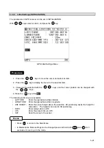
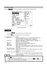
Selecting NEXT in “5.3.6 System” allows you to continue system settings.
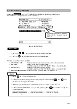
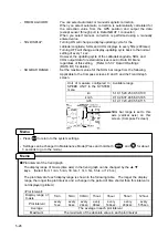
1. Press to move the cursor and select an item in the menu.
2. Press to display menu for the selected item.
The following submenus are available.
•
RPEVIOUS:
Goes to the previous page (Refer to the previous page.)
•
HVE BAR RANGE:
Set the maximum value for the heaving bar graph, displayed
on the Compass screens D, E, and F, and the Trend Graph screen
(Select from 1, 2, 3, 4, 5, 10, 20, 30, 40, 50, or 100m.)
•
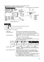
HVE BAR DISPLAY:
Select the type of heaving bar displayed on the Compass screens D
and E.
・
OFF Heaving bar is not displayed.
・
DISPLAY 1 - 4 Refer to the following figure.
(The Compass screen F turns the display off when OFF is selected,
otherwise, displays the DISP1.)
•
TREND GRAPH :
AVERAGE: Displays the average value of each sampling zone.
MAXIMUM: Displays the maximum value of the absolute value of
each sampling zone.
•
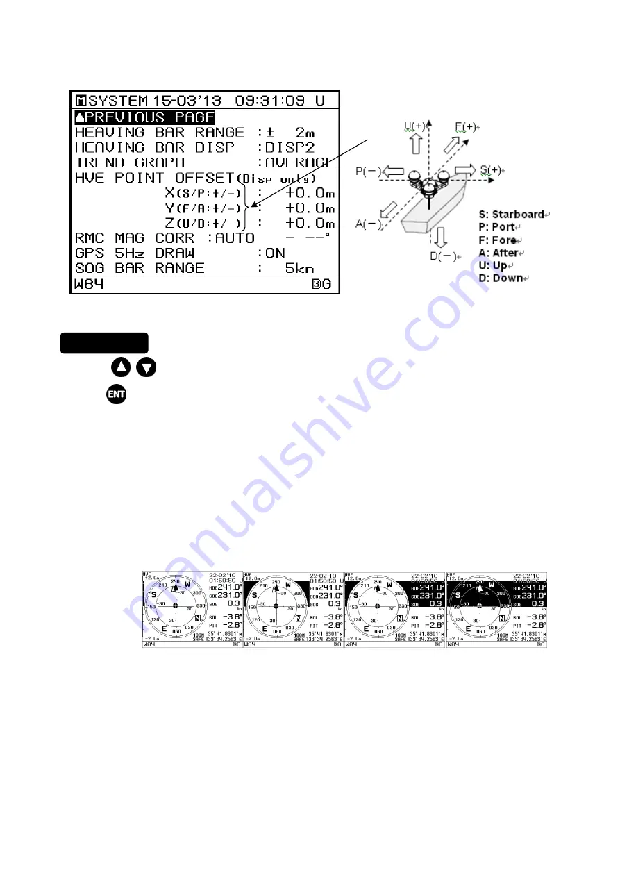
HVE POSITION OFFSET : Applicable to a heaving bar display and a trend graph display
only, excluding any external output. A desired offsetting position is
specified by the following polarities on the basis of the installation
position of the sensor unit of the device.
X: + for offsetting to the starboard side, - for offsetting to the port side.
Y: + for offsetting to the bow side, - for offsetting to the stern side.
Z: + for offsetting upward, - for offsetting downward.
Refer to the above “Polarity Illustration for Inputting Offset” for details.
< Polarity Illustration for Inputting Offset >
System Settings Screen
Procedure
DISP
1
DISP2
DISP3
DISP4
Summary of Contents for jlr-21
Page 2: ......
Page 30: ...2 12 About NNN 31 ...
Page 31: ...2 13 ...
Page 32: ...2 14 About Bird Repellent Rod MPXP34012A MPXP34012A ...
Page 54: ...3 4 ...
Page 62: ...4 8 ...
Page 114: ...7 2 ...
Page 116: ...8 2 ...
Page 120: ...9 4 ...
Page 122: ...Appendix 1 2 ...
Page 138: ...Appendix 3 4 ...
Page 142: ...Appendix 4 4 ...
Page 146: ......
Page 147: ......


