3-60
7
࠙
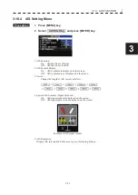
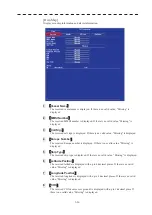
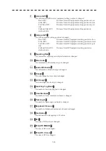
Internal GPS
ࠚ
The AIS(internal GPS device) equipment setting position is changed.
Bow-GPS :
Distance from AIS equipment setting position to bow
Stern-GPS :
Distance from AIS equipment setting position to stern
Port Side-GPS :
Distance from AIS equipment setting position to port
side
Starboad Side-GPS :
Distance from AIS equipment setting position to
starboard side
8
࠙
External GPS
ࠚ
The GPS equipment setting position is changed.
Bow-GPS :
Distance from GPS equipment setting position to bow
Stern-GPS :
Distance from GPS equipment setting position to stern
Port Side-GPS :
Distance from GPS equipment setting position to port
side
Starboad Side-GPS :
Distance from GPS equipment setting position to
starboard side
9
࠙
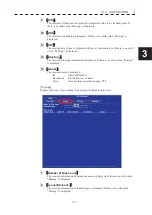
Reporting Rate
ࠚ
The interval for reporting own ship information is changed.
10
࠙
Blue Cones
ࠚ
The information of hazardous cargo is changed.
11
࠙
Loaded/Unloaded
ࠚ
The information of loaded cargo is changed.
12
࠙
Draught
ࠚ
The static draught of own ship is changed.
13
࠙
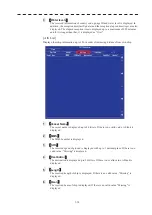
Air Draught
ࠚ
The air draught of own ship is changed.
14
࠙
Assisting Tug Boats
ࠚ
The number of assisting tugboat is changed.
15
࠙
Crew Members
ࠚ
The number of crew members on board is changed.
16
࠙
Passengers
ࠚ
The number of passengers on board is changed.
17
࠙
Shipboard Personal
ࠚ
The number of shipboard personnel on board is changed.
18
࠙
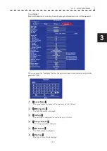
Destination
ࠚ
The destination is changed up to 20 letters.
19
࠙
ETA
ࠚ
The state of ETA value is changed.
20
࠙
ETA(UTC MM/DD)
ࠚ
The date of ETA is changed.
21
࠙
ETA(UTC hh:mm)
ࠚ
The time of ETA is changed.
Summary of Contents for JMR-611
Page 2: ......
Page 24: ......
Page 26: ......
Page 28: ......
Page 33: ...1 5 1 1 4 EXTERIOR DRAWINGS y Fig 1 1 Exterior Drawing of Scanner Unit Type NKE 387 Unit mm...
Page 34: ...1 6 Fig 1 2 Exterior Drawing of Processing Unit Type NDC 1774 Unit mm...
Page 35: ...1 7 1 1 4 EXTERIOR DRAWINGS y Fig 1 3 Exterior Drawing of Operating Unit Type NCE 5923 Unit mm...
Page 38: ......
Page 54: ......
Page 116: ......
Page 118: ......
Page 124: ......
Page 134: ......
Page 136: ......
Page 142: ......
Page 144: ......
Page 154: ......
Page 156: ......
Page 160: ......
Page 164: ......
Page 166: ......
Page 172: ......
Page 174: ......
Page 177: ...APPENDIX Fig 1 Block Diagram of JMR 611...
Page 181: ...APPENDIX Fig 5 Internal Connection Diagram of Control Unit NCM 994...
Page 182: ......
Page 184: ......
Page 186: ......
Page 187: ......

