4.3 MEASUREMENT BY EBL AND VRMS
y
yyy
4-3
4
4.3
MEASUREMENT BY EBLS AND VRMS
Procedures
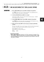
1 Press [EBL1/EBL2] key to select EBL1 display and operation.
The EBL1 button at the lower left of the radar display will be highlighted and the
EBL1 will appear as a broken-line on the PPI display.
2 Turn the [JOG DIAL] to put EBL1 on a target.
The bearing of the EBL1 will appear at the lower left of the radar display. The EBL1
bearing represents the target’s bearing.
3 Press [VRM1/VRM2] key to select VRM1 display and operation.
The VRM1 button at the lower right of the radar display will be highlighted and the
VRM1 will appear as a broken-line circle on the PPI display.
4 Move the broken-line VRM1 to the target by using the [JOG DIAL]
control.
The range of the VRM1 from own ship will appear at the lower right of the radar display.
The range of VRM1 indicates a distance between the target and own ship.
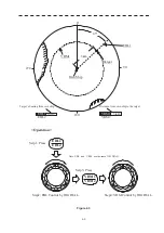
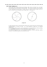
Refer to
Figure 4.3
in the next page.
In this Figure 4.3, the range and bearing are;
Range: 3km
Bearing: 45.0
q
Important information
EBL or VRM of JOG DIAL operation can be also operated by Trackball. If you
operated EBL or VRM at the last time, you must fix the position of EBL or VRM
by pressing ENTER key. Otherwise, the position that you decided is moved by
JOG DIAL or Trackball.
Summary of Contents for JMR-611
Page 2: ......
Page 24: ......
Page 26: ......
Page 28: ......
Page 33: ...1 5 1 1 4 EXTERIOR DRAWINGS y Fig 1 1 Exterior Drawing of Scanner Unit Type NKE 387 Unit mm...
Page 34: ...1 6 Fig 1 2 Exterior Drawing of Processing Unit Type NDC 1774 Unit mm...
Page 35: ...1 7 1 1 4 EXTERIOR DRAWINGS y Fig 1 3 Exterior Drawing of Operating Unit Type NCE 5923 Unit mm...
Page 38: ......
Page 54: ......
Page 116: ......
Page 118: ......
Page 124: ......
Page 134: ......
Page 136: ......
Page 142: ......
Page 144: ......
Page 154: ......
Page 156: ......
Page 160: ......
Page 164: ......
Page 166: ......
Page 172: ......
Page 174: ......
Page 177: ...APPENDIX Fig 1 Block Diagram of JMR 611...
Page 181: ...APPENDIX Fig 5 Internal Connection Diagram of Control Unit NCM 994...
Page 182: ......
Page 184: ......
Page 186: ......
Page 187: ......

