10.3 CONTROL UNIT(NCM-994)
yy
yyyy
yyyy
10-3
10
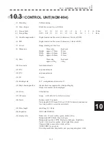
10.3
CONTROL UNIT(NCM-994)
(1) Mounting
Table mounting
(2) Video Output
RGB, H-sync and V-sync (SXGA)
(3) Range
Scale
0.1 0.2 0.3 0.4 0.5 0.8 1.2 1.6 2 4 8 16 32km
(4) Range
Ring
0.025 0.05 0.1 0.1 0.1 0.2 0.2 0.4 0.4 1 2 4 8km
(5) Variable range marker
Digital read-out on the screen (4 characters) 2 kinds of VRM
(6) EBL
Digital read-out on the screen (4 characters) 2 kinds of EBL
(7) Cursor
Range, Bearing, and Lat./Lon.
(8) Dimension
Processing
Keyboard
Height:
approx.
170mm 45mm
Width:
approx.
360mm 290mm
Depth:
approx.
340mm 123mm
(9) Mass
Processing
Keyboard
approx.
6.9kg 1.0kg
(10) Tune mode
Auto/manual mode
(11) STC
only manual mode
(12) FTC
only manual mode
(13) IR
3 levels
(14) Bearing scale
360
r
scale graduate at intervals of 1
r
(15) Ship’s heading marker
Electric flash line suppressible while pushing key
Ship’s stern marker can be displayed.
(16) P-Line
2 Parallel line
(17) Off center
3steps +60%,40%,20% of effective radius.
(18) Trails
Relative trails / True trails
Trails length: OFF/2 scans/15/30sec/1/2/3/4/5/6min and continuation.
Any time possible to select the said article.
(19) Pulse length
short/long (2, 4, 8km)
(20) Expansion
OFF/FAIR/STRONG
(21) display color
Radar echo: 16 level (yellow, green, amber, white)
Background (PPI): black, blue, dark gray
Background (outside of PPI): black, gray, dark gray, bright blue
Trails: 16 level (yellow, amber, white, bright blue, green)
Character/Dial: green, amber, white, yellow,
VRM1/VRM2: cyan, green
Own ship mark/ other ship mark: cyan, gray, magenta, green, white
Summary of Contents for JMR-611
Page 2: ......
Page 24: ......
Page 26: ......
Page 28: ......
Page 33: ...1 5 1 1 4 EXTERIOR DRAWINGS y Fig 1 1 Exterior Drawing of Scanner Unit Type NKE 387 Unit mm...
Page 34: ...1 6 Fig 1 2 Exterior Drawing of Processing Unit Type NDC 1774 Unit mm...
Page 35: ...1 7 1 1 4 EXTERIOR DRAWINGS y Fig 1 3 Exterior Drawing of Operating Unit Type NCE 5923 Unit mm...
Page 38: ......
Page 54: ......
Page 116: ......
Page 118: ......
Page 124: ......
Page 134: ......
Page 136: ......
Page 142: ......
Page 144: ......
Page 154: ......
Page 156: ......
Page 160: ......
Page 164: ......
Page 166: ......
Page 172: ......
Page 174: ......
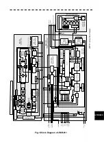
Page 177: ...APPENDIX Fig 1 Block Diagram of JMR 611...
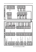
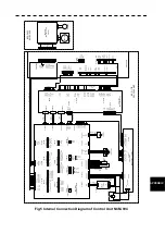
Page 181: ...APPENDIX Fig 5 Internal Connection Diagram of Control Unit NCM 994...
Page 182: ......
Page 184: ......
Page 186: ......
Page 187: ......


