10.5 OUTPUT SIGNAL
yy
yyyy
yyyy
10-5
10
10.5
OUTPUT
SIGNAL
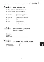
(1) The signal for Slave Display TIY, VD, BP (2048 pulse), BZ
(2) Navigation information
RADAR system data: RSD
Own ship data: OSD
(3) External alarm
Point-of-contact signal normal close.
Max current : 200mA.
(4) 2ND monitor
Analog RGB HD 15pin connector 1pcs
(DVI connector 1pcs.)
(5) AIS ACK.
(6) LAN
100Mbps(100BACE-TX)
Radar screen
UDP/IP Multi cast.
Sweep/quadrant /full screen/block
Radar control TCP/IP Uni cast.
All the operation except power on/off.
10.6
STANDARD
EQUIPMENT
COMPOSITION
Scanner unit: 1
Process unit: 1
Operation unit: 1
Spare parts: 1
Instruction manual:1
10.7
DISTANCE
BETWEEN
UNITS
Standard
Monitor-processor unit
5m
Keyboard-processor unit
7m
Scanner-processor unit
20m
Summary of Contents for JMR-611
Page 2: ......
Page 24: ......
Page 26: ......
Page 28: ......
Page 33: ...1 5 1 1 4 EXTERIOR DRAWINGS y Fig 1 1 Exterior Drawing of Scanner Unit Type NKE 387 Unit mm...
Page 34: ...1 6 Fig 1 2 Exterior Drawing of Processing Unit Type NDC 1774 Unit mm...
Page 35: ...1 7 1 1 4 EXTERIOR DRAWINGS y Fig 1 3 Exterior Drawing of Operating Unit Type NCE 5923 Unit mm...
Page 38: ......
Page 54: ......
Page 116: ......
Page 118: ......
Page 124: ......
Page 134: ......
Page 136: ......
Page 142: ......
Page 144: ......
Page 154: ......
Page 156: ......
Page 160: ......
Page 164: ......
Page 166: ......
Page 172: ......
Page 174: ......
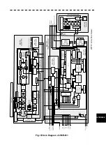
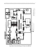
Page 177: ...APPENDIX Fig 1 Block Diagram of JMR 611...
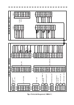
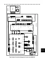
Page 181: ...APPENDIX Fig 5 Internal Connection Diagram of Control Unit NCM 994...
Page 182: ......
Page 184: ......
Page 186: ......
Page 187: ......

