2-10
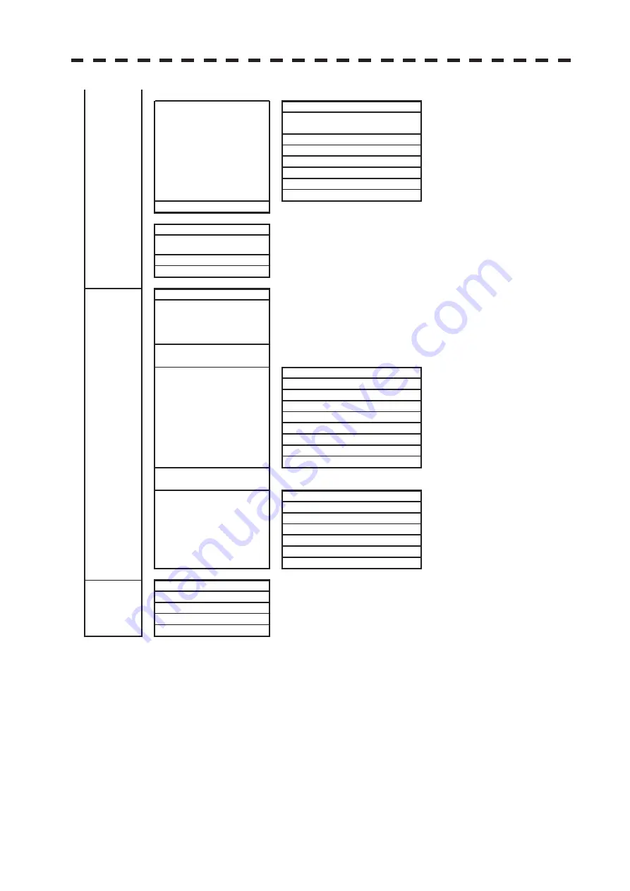
5.File Operations >
䊻
0.Previous
1.Select Card Slot
Slot1/Slot2/
Internal
2.Load Mode
Overwrite/Add
3.Load
4.Unload
5.Save
6.Erase
7.File Mark Display
6,Next >
䊼
6.Next
0.Previous
1.Own Ship Position
84°59.999 N ~ 84°59.999 S
180°00.000 E ~ 180°00.000 W
2.Geodetic
3.Own Ship Heading
0.0 ~ 359.9°
5.Own Track
䊻
0.Previous
1.Plot Interval
Off/3sec/5sec/10sec/30sec/1min/
3min/5min/10min/30min/60min/
0.1km/0.2km/0.3km/0.5km/1km/
3km/5km/10km
2.Plot Color
Off/White/Cyan/Blue/Green/
Yellow/Pink/Red
䊻
0.Previous
1.All
Off/On/Individual
2.White
Off/On
3.Cyan
Off/On
4.Blue
Off/On
5.Green
Off/On
6.Yellow
Off/On
7.Pink
Off/On
8.Red
Off/On
4.Delete Own Track Color
ALL/White/Cyan/Blue/Green/
Yellow/Pink/Red
䊻
0.Previous
1.Select Card Slot
Slot1/Slot2
2.Load Mode
Overwrite/Add
3.Load
4.Save
5.Erase
6.File Own Track Display
6.Mile Maker
䊻
0.Previous
1.Display
Off/On
2.Select Card Slot
Slot1/Slot2
3.Load Mode
Overwrite/Add
4.Load
3.Display Own
Track Color >
5.File Operations >
Summary of Contents for JMR-611
Page 2: ......
Page 24: ......
Page 26: ......
Page 28: ......
Page 33: ...1 5 1 1 4 EXTERIOR DRAWINGS y Fig 1 1 Exterior Drawing of Scanner Unit Type NKE 387 Unit mm...
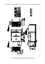
Page 34: ...1 6 Fig 1 2 Exterior Drawing of Processing Unit Type NDC 1774 Unit mm...
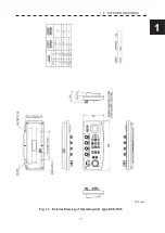
Page 35: ...1 7 1 1 4 EXTERIOR DRAWINGS y Fig 1 3 Exterior Drawing of Operating Unit Type NCE 5923 Unit mm...
Page 38: ......
Page 54: ......
Page 116: ......
Page 118: ......
Page 124: ......
Page 134: ......
Page 136: ......
Page 142: ......
Page 144: ......
Page 154: ......
Page 156: ......
Page 160: ......
Page 164: ......
Page 166: ......
Page 172: ......
Page 174: ......
Page 177: ...APPENDIX Fig 1 Block Diagram of JMR 611...
Page 181: ...APPENDIX Fig 5 Internal Connection Diagram of Control Unit NCM 994...
Page 182: ......
Page 184: ......
Page 186: ......
Page 187: ......

