3-3
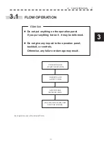
3.1 FLOW OPERATION
y
yy
3
Procedures
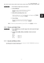
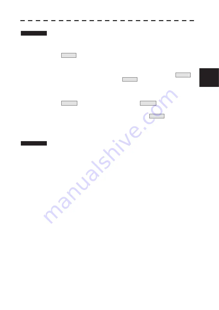
1 Check that the ship’s mains are turned on.
2 Press [STBY] key.
The system is turned on, and the preheating time is displayed.
Preheat is indicated at the lower left of the screen.
3 Wait until the preheating time is over.
When the preheating time is over, the preheating time screen disappears, and Preheat
at the lower left of the screen changes to Standby .
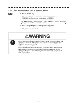
4 Press [TX] key.
The radar will start transmission and the antenna will start rotating.
Standby at the lower left of the screen changes to Transmit .
Note:
The radar does not start transmission if you press [TX] key while Preheat is indicated.
3.1.2 Observe and Adjust Video
Procedures
1 Press [+RANGE-] key to set the range to the scale required for target
observation.
2 Turn the dials [GAIN], [SEA], and [RAIN] to obtain the clearest
targets.
Refer to
[GAIN]
Ѝ
Chapter 3.4.5
[SEA]
Ѝ
Chapter 3.4.6
[RAIN]
Ѝ
Chapter 3.4.7
3.1.3 Acquire and Measure Data
For details on how to acquire data and measure, refer to Section 3.4 “BASIC OPERATIONS” and Section 4
“MEASUREMENT OF RANGE AND BEARING.”
Summary of Contents for JMR-611
Page 2: ......
Page 24: ......
Page 26: ......
Page 28: ......
Page 33: ...1 5 1 1 4 EXTERIOR DRAWINGS y Fig 1 1 Exterior Drawing of Scanner Unit Type NKE 387 Unit mm...
Page 34: ...1 6 Fig 1 2 Exterior Drawing of Processing Unit Type NDC 1774 Unit mm...
Page 35: ...1 7 1 1 4 EXTERIOR DRAWINGS y Fig 1 3 Exterior Drawing of Operating Unit Type NCE 5923 Unit mm...
Page 38: ......
Page 54: ......
Page 116: ......
Page 118: ......
Page 124: ......
Page 134: ......
Page 136: ......
Page 142: ......
Page 144: ......
Page 154: ......
Page 156: ......
Page 160: ......
Page 164: ......
Page 166: ......
Page 172: ......
Page 174: ......
Page 177: ...APPENDIX Fig 1 Block Diagram of JMR 611...
Page 181: ...APPENDIX Fig 5 Internal Connection Diagram of Control Unit NCM 994...
Page 182: ......
Page 184: ......
Page 186: ......
Page 187: ......


