iv
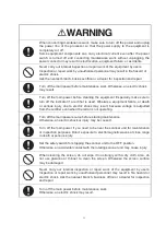
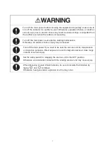
When conducting maintenance work, make sure to turn off the power and unplug
the power line of the processor so that the power supply to the equipment is
completely cut off.
Some equipment components can carry electrical current even after the power
switch is turned off and conducting maintenance work without unplugging the
power connector may result in electrocution, equipment failure, or accidents.
Never carry out internal inspection or repair work of the equipment by users.
Inspection or repair work by unauthorized personnel may result in fire hazard or
electric shock.
Ask the nearest branch, business office or a dealer for inspection and repair.
Turn off the main power before maintenance work. Otherwise, an electric shock
may result.
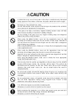
Turn off the main power before cleaning the equipment. Especially, make sure to
turn off the indicator if a rectifier is used. Otherwise, equipment failure, or death
or serious injury due to electric shock may result, because voltage is outputted
from the rectifier even when the radar is not operating.
Turn off the main power source before starting maintenance.
Otherwise, an electric shock or injury may be caused.
Turn off the main power if you need to be near the scanner unit for maintenance
or inspection purposes. Direct exposure to electromagnetic waves at close range
in death or serious injury.
Set the safety switch for stopping the scanner unit to the OFF position.
Otherwise, an accidental contact with the rotating scanner unit may cause injury.
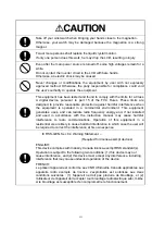
When cleaning the screen, do not wipe it too strongly with a dry cloth. Also, do
not use gasoline or thinner to clean the screen. Otherwise the screen surface
may be damaged.
Never carry out internal inspection or repair work of the equipment by users.
Inspection or repair work by unauthorized personnel may result in fire hazard or
electric shock. Ask the nearest branch, business office or a dealer for inspection
and repair.
Turn off the main power before maintenance work.
Otherwise, an electric shock may result.
Summary of Contents for JMR-611
Page 2: ......
Page 24: ......
Page 26: ......
Page 28: ......
Page 33: ...1 5 1 1 4 EXTERIOR DRAWINGS y Fig 1 1 Exterior Drawing of Scanner Unit Type NKE 387 Unit mm...
Page 34: ...1 6 Fig 1 2 Exterior Drawing of Processing Unit Type NDC 1774 Unit mm...
Page 35: ...1 7 1 1 4 EXTERIOR DRAWINGS y Fig 1 3 Exterior Drawing of Operating Unit Type NCE 5923 Unit mm...
Page 38: ......
Page 54: ......
Page 116: ......
Page 118: ......
Page 124: ......
Page 134: ......
Page 136: ......
Page 142: ......
Page 144: ......
Page 154: ......
Page 156: ......
Page 160: ......
Page 164: ......
Page 166: ......
Page 172: ......
Page 174: ......
Page 177: ...APPENDIX Fig 1 Block Diagram of JMR 611...
Page 181: ...APPENDIX Fig 5 Internal Connection Diagram of Control Unit NCM 994...
Page 182: ......
Page 184: ......
Page 186: ......
Page 187: ......


