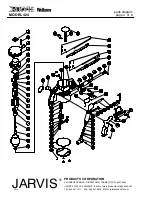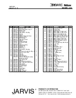
page 5 of 8
MODEL 424
PRODUCTS CORPORATION
33 ANDERSON ROAD, MIDDLETOWN, CONNECTICUT 06457-4926
UNITED STATES OF AMERICA E--MAIL.
jarvis.products.corp@snet.net
TEL. 860-347-7271 FAX. 860-347-6978 WWW.
jarvisproducts.com
JARVIS
6205001a
®
1
1017083
Danger Label
1
2
1055427
Flat Head Screw, Pkg. 12
4
3
1061186
Plastic Plug
1
4
1002191
Top Cover
1
5
1016206
Upper Motor Housing
1
6
1035259
O--ring
1
7
1014079
Spring
1
8
1073185
Socket Head Cap Screw
2
9
1013135
Retaining Ring
1
10
1021225
Ball Bearing
1
11
1032147
Upper End Plate
1
12
1010178
Roll Pin
2
13
1009077
Cylinder Sleeve
1
14
1040007
Air Motor Vanes
5
15
1064015
Rotor
1
16
1032146
Lower End Plate
1
17
1021551
Ball Bearing
1
18
1020131
Spindle
1
19
1026072
Pinion Gear
1
20
1016205
Lower Motor Housing
1
21
1035193
Seal
1
22
1055426
Flat Hd Scr & Lk Wshr, Pkg.12
4
23
1002193
Bottom Cover Plate
1
24
1035191
Gasket
1
25
1007164
Lock Nut
2
26
1021228
Needle Bearing
2
3028030
Rod and Bearing Assembly
(items 26 and 27)
27
1028060
Connecting Link
1
28
1029185
Spacer
1
29
1013310
External Retaining Ring
1
30
3026023
Gear, Bearing & Stud Assy
1
31
1020133
Gear Shaft
1
32
1021218
Thrust Bearing
1
33
1004149
Thrust Washer
1
34
1050236
Elbow
1
35
1050235
Long Nipple
1
36
1007162
Cap Nut
6
37
1007166
Gear Stud Nut
1
38
1016202
Saw Housing
1
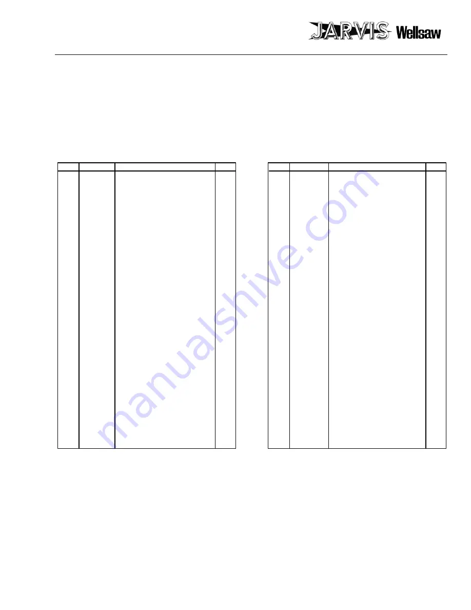
ITEM PART NO.
PART NAME
QTY
ITEM PART NO.
PART NAME
QTY
39
1055429
Oval Head Screw
2
40
1027042
Handle Stud
1
41
1006021
Handle Knob
1
42
1058071
Blade Support, End Cut 8”
1
1058070
Blade Support, End Cut 16”
43
1023122
Blade, End Cutting 8 inch
1
1023121
Blade, End Cutting 16 inch
44
1058075
Blade Support, Heavt Duty, 8”
1
1058074
Bl Support, Heavy Duty, 16”
45
1023123
Blade, Heavy Duty 8 inch
1
1023124
Blade, Heavy Duty 16 inch
46
1055422
Socket Set Screw, Cup Pt.
1
47
1012050
Clamp Ring
1
48
3065010
Rod & Stud Assy with item 49
1
49
1027041
Drive Stud
1
50
1035192
Seal
2
51
1036116
Bushing
1
52
1017039
Nameplate Label
1
1017037
Wellsaw Label
1
53
1036120
Bushing
3
54
1012047
“U” Clip (rubber)
1
55
1012046
“S” Clip
1
56
1027048
Threaded Stud
3
57
1045013
Rivet
4
58
8030031
Hex Key
1
59
1002206
Blade Support Cover
1
60
1035126
IO--ring
2
61
1051050
Air Tube
1
62
1039032
Trigger Plunger
1
63
1021214
Bushing
1
64
1016203
Valve Housing with item 65
1
65
1055435
Locking Socket Set Screw
1
66
1022060
Valve Seat
1
67
1035064
O--ring
3
68
1022059
Air Valve
1
69
1014078
Compression Spring
1
70
1015007
Screen
1
71
1016204
Lower Valve Body
1
72
1055439
Oval Head Screw
6
73
1002200
Handle Cover
1
parts list


