page 7 of 8
MODEL 424
PRODUCTS CORPORATION
33 ANDERSON ROAD, MIDDLETOWN, CONNECTICUT 06457-4926
UNITED STATES OF AMERICA E--MAIL.
jarvis.products.corp@snet.net
TEL. 860-347-7271 FAX. 860-347-6978 WWW.
jarvisproducts.com
JARVIS
6205001a
®
4.1 Your power hand saw is not designed for regular
use in starting its own hole by sinking blades
through a surface, commonly called “plunge
cutting”. If attempted, the operator must:
a. Keep the saw blade as parallel to the work
as possible.
b. Immediately, as the blade makes contact
with the work piece, start to draw the saw
back slowly from the starting point.
c. Repeat the operation outlined in “b”, if nec-
essary.
d. Have room to draw the saw at least 4--6 in-
ches before cutting through a one inch
thickness.
e. Do not force the saw blade, but keep it
moving slowly on the draw back from the
starting point. After a break through cut
has been made and the end of the blade sup-
port extends through the material at least
1--1/2 inches, the saw may be tipped to a
normal cutting angle.
5 ALWAYS KEEP A SHARP BLADE ON THE
SAW:
5.1 Cutting with a dull or badly worn blade can
overload the saw and cause damage from over-
heating.
5.2 New blades can be purchased from
Jarvis
.
MAINTENANCE INSTRUCTIONS
IMPORTANT: ALWAYS DISCONNECT THE COM-
PRESSED AIR SUPPLY IN ACCORDANCE WITH
OSHA’S LOCKOUT/TAGOUT PROCEDURES (29 CFR
1910.147) WHEN INSTALLING OR REMOVING THE
BLADE. ALWAYS DISCONNECT THE AIR SUPPLY IN
ACCORDANCE WITH OSHA’S LOCKOUT/TAGOUT
PROCEDURES (29 CFR 1920.147) BEFORE PERFORM-
ING ANY MAINTENANCE OR REPAIRS
.
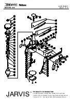
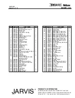
Item numbers: refer to the parts diagram on page 4.
1 DAILY:
1.1 Inspect all hoses for cuts and abrasions and re-
place as necessary.
1.2 Check all fittings and connections for leaks and
tighten or replace as necessary.
1.3 An air filter/regulator/lubricator (
Jarvis
part
number 3022003) must be installed in the air
supply line.
Keep the lubricator filled at all
times
.
1.4 Make sure that the saw is working correctly.
Note: The air supply must be connected to per-
form this maintenance check only.
Depress
the trigger and the tool should start.
Release
the trigger and the tool should stop.
If
the tool malfunctions, repair or remove it from
service immediately.
Always use two hands when starting and stop-
ping the tool. Continue holding the saw firmly
with both hands until the blade comes to a com-
plete stop
.
2 WEEKLY:
2.1 Remove the bottom cover plate from saw hous-
ing (item 38).
2.2 Apply
Jarvis
1315 White Grease
to the pinion
and gear, bearing and stud assembly (items 19
and 30).
3 MONTHLY:
3.1 The gear case should be kept 1/3 full of grease.
To check the grease level, remove the bottom
cover plate (item 23) and its gasket (item 24).
Check more frequently for saws that are used
daily. Use
Jarvis
1315 White Grease.
4 BLADE REMOVAL:
NOTE: Your
Jarvis
Wellsaw is equipped with a hex key
(item 58) for removing the blade. This wrench is located
in the housing directly behind the blade support.
4.1 Insert the hex key through the hole in the outer
end of blade (item 43) and pull the blade to the
outer end of its stroke.
operation and
maintenance instructions


