parts diagram and list,
specifications and installation instructions
Model 700-FS and 900--FS
page 9 of 12
JARVIS
6207014::::
®
PRODUCTS CORPORATION
33 ANDERSON ROAD, MIDDLETOWN, CONNECTICUT 06457--4926
UNITED STATES OF AMERICA E--MAIL.
jarvis.products.corp@snet.net
TEL. 860-347-7271 FAX. 860-347-6978 WWW
.jarvisproducts.com
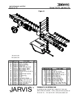
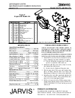
1
1055283
Hex Head Screw
2
2
1024149
Trigger Guard
1
3
1018131
Trigger Lever
1
4
1019150
Handle
1
5
1055398
Socket Head Cap Screw
4
6
1010286
Dowel Pin
1
7
1061630
Hydraulic Manifold
1
8
1012088
Clamp Bracket
1
9
1055312
Set Screw
1
10
1051150
Plug
1
11
1035245
O--ring
1
12
1014086
Spring
1
13
1039034
Valve Plunger with item 14
1
14
1035279
O--ring
1
3019151
Ergonomic Handle Kit
(items 1--14)
ITEM PART NO.
PART NAME
QTY
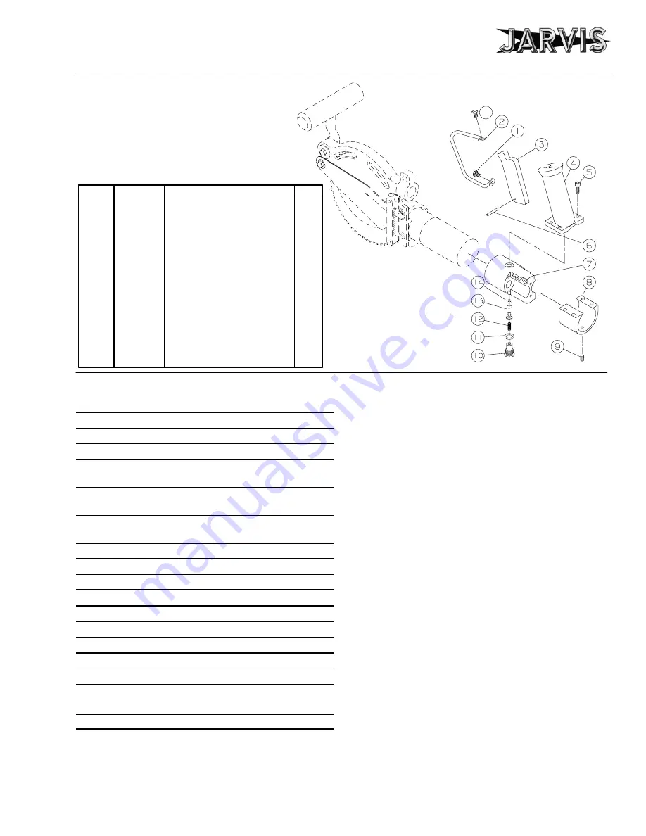
Figure F
Ergonomic Handle Kit
Model 700--FS shown above.
SPECIFICATIONS
Model 700-FS and 900--FS
Motor Power
2.5 hp
1867 W
Blade Speed
at 3.5 gpm
2200 rpm
Control Handle
Single / Pneumatic
Blade Diameter (700FS)
6.5 in
165 mm
Blade Diameter (900FS)
8.0 in
203 mm
Cutting Depth (max. 700FS) 1.9 in
48 mm
Cutting Depth (max. 900FS) 2.6 in
67 mm
Overall Length (700FS)
17 in
425 mm
Overall Length (900FS)
18.75 in
476 mm
Weight (with hoses)
10 lbs
4.7 kg
Vibration
less than (<) 120 dB
< 1.0 m/sec
2
Noise
(one meter from tool)
88 dB
Hydraulic Power Unit
Motor Power
5 hp
3728 W
Operating Voltage
230/460 V, 3 ph, 60 Hz
Hose Length
16 ft
5 m
Oil Capacity
20 gal
76 L
Oil Visc. at 100
°
F/40
°
C 200 SUS
46 ISO
Overall Dimensions (l x w x h)
28 x 23 x 28 in
711 x 584 x 711 mm
Weight (without oil)
200 lbs
91 kg
INSTALLATION INSTRUCTIONS
ALWAYS DISCONNECT THE POWER SUPPLY IN
ACCORDANCE WITH OSHA’S LOCKOUT/TAGOUT
PROCEDURES (29 CFR 1910.147) BEFORE PERFORM-
ING ANY REPAIRS OR MAINTENANCE.
ALL WIRING MUST BE DONE IN ACCORDANCE WITH
NATIONAL, STATE AND LOCAL ELECTRICAL CODES.
1 Install the FS saw above the work station from a ba-
lancer.
Jarvis
part number 4042044 is available.
1.1 The saw should have enough travel to allow the
operator to reach the entire work area.
2 Install the hydraulic power unit overhead or on the
floor behind the work station.
2.1 Avoid excessive height and long pipe runs.
3 Wire the power unit. The power unit requires three
phase, 60 Hertz, 230/460 volts to the motor and
single phase, 60 Hertz, 115 volts to the control box.
4 Equip the power unit with a master pilot light switch
at the operator’s station.
This will facilitate shut-
down in case of an equipment failure.
5 Fill the oil reservoir with a USDA approved pre-
mium grade hydraulic fluid (viscosity: 200 S.U.S. at
100
°
F or 46 ISO at 40
°
C).
Never run the power unit
without oil.


