maintenance instructions
Model MCS 300
page 11 of 16
®
JARVIS
6201010:.
PRODUCTS CORPORATION
33 ANDERSON ROAD, MIDDLETOWN, CONNECTICUT 06457--4926
UNITED STATES OF AMERICA E--MAIL.
jarvis.products.corp@snet.net
TEL. 860--347--7271 FAX. 860--347--6978 WWW. j
arvisproducts.com
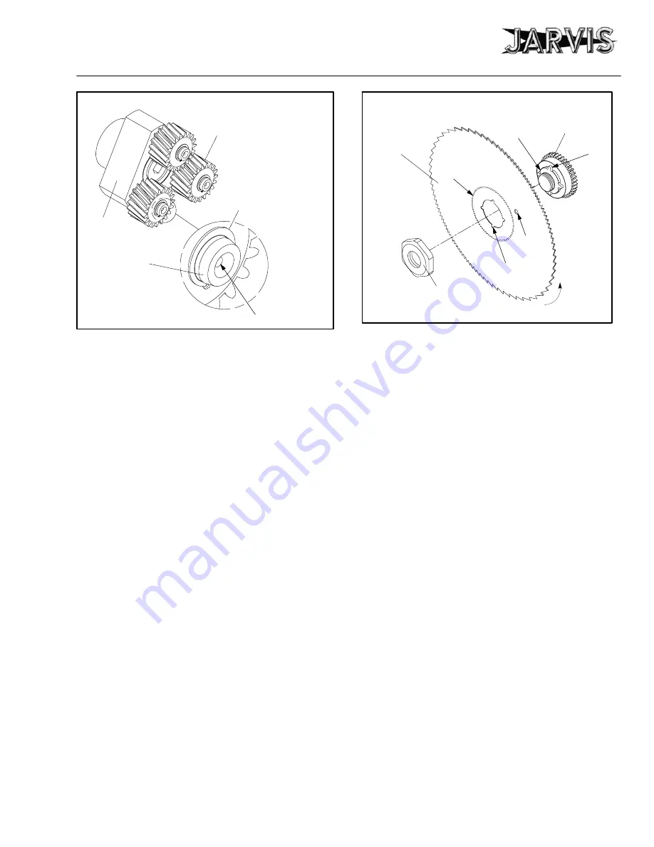
Figure 1
Bearing and Gear Lubrication
PLANET GEAR
HOLE TO
LUBRICATE
NEEDLE BEARING
DOWEL PIN
RETAINING
RING
PLANETARY
HUB
3 AS NECESSARY:
3.1 Clean and inspect circular blade.
Refer to sec-
tions 4 and 5 for blade removal and installation
procedures.
3.2 Disassemble, clean and inspect the spur gear
housing assembly, planetary housing assembly,
air motor assembly, and handle and valve hous-
ing assembly.
Refer to sections 6 through 12 as
a procedural guide.
4 CIRCULAR BLADE REMOVAL:
4.1 Remove locking lever (item 1), depth gage
screw (item 2) and depth gage plate (item 3) if
applicable.
4.2 Remove the blade nut (item 4).
Jarvis
wrench
1061361 is available.
See Figure E on page 8.
4.2.1 Place an awl or small screwdriver through
the outer hole in blade to prevent it from ro-
tating.
4.3 Remove the saw blade (item 5) and sharpen or
replace as necessary.
5 CIRCULAR BLADE INSTALLATION:
5.1 Reverse procedures and steps outlined in section
4.
See notes below. Refer to Figure 2 as a guide.
5.1.1 To ensure proper fit and safe operation, the
hub of the saw blade (item 5) must face to-
ward and fit securely on the extended lip of
the spur gear.
5.1.2 Make sure notched areas on the saw blade
are aligned with ears on the spur gear.
LIP
BLADE
BLADE
NUT
SPUR
GEAR
EAR
OUTER
HOLE
HUB ON
OTHER
SIDE
NOTCHED
AREA
Figure 2
Blade Installation
BLADE
ROTATION
DIRECTION
5.1.3 When tightening blade nut (item 4), insert
an awl or small screwdriver through the out-
er hole in the blade to prevent blade from
turning.
Jarvis
wrench 1061361 is avail-
able.
See Figure E on page 8.
6 SPUR GEAR HOUSING DISASSEMBLY:
6.1 Remove blade as described in section 4.
6.2 Remove flat head screws (item 55).
6.3 Remove blade guard assembly and auxiliary
handle assembly (items 6--9) as a complete unit
from spur gear housing (item 18).
6.4 Remove dowel pins, o--ring and u--cup seal
(items 10--12) from blade guard only if neces-
sary.
6.5 Remove cheese head screws (item 77) and lock
washers (item 76). Remove spur gear housing
(item 18) and planetary housing (item 45) as a
complete unit from motor housing (item 60).
6.5.1 Set motor housing and rear handle assembly
aside.
6.6 Remove hex head screws (item 30) and lock
washers (item 29). Separate planetary housing
assembly (items 24--45) as a complete unit from
spur gear housing (item 18).
6.7 Remove spur gear hex nut (item 20),
left hand
thread.
6.7.1 Use a 5 mm allen wrench to hold spur gear
pin (item 14) from moving while unscrew-
ing spur gear hex nut (item 20),
left hand
thread. Note: Use heat to loosen hex nut if
necessary
.


