maintenance instructions
Model MCS 300
page 15 of 16
®
JARVIS
6201010:.
PRODUCTS CORPORATION
33 ANDERSON ROAD, MIDDLETOWN, CONNECTICUT 06457--4926
UNITED STATES OF AMERICA E--MAIL.
jarvis.products.corp@snet.net
TEL. 860--347--7271 FAX. 860--347--6978 WWW. j
arvisproducts.com
8.4 Remove retaining rings (item 38).
8.5 Remove planetary gear pins (item 41), planet
gears (item 39) and needle bearings (item 40)
from planetary gear hub (item 35).
Use a drive
punch if necessary.
8.6 Remove planetary gear pins (item 41) and
needle bearings (item 40) from planet gears
(item 39).
Jarvis
special tool 8039168 is avail-
able.
See Figure E on page 8. Be careful not to
score any parts.
8.7 Remove retaining ring (item 34).
8.8 Remove pinion gear (item 43), ball bearing
(item 33), inner race (item 42) and key (item 32)
from planetary housing (item 45).
Lightly tap
gear housing end of planetary housing with ny-
lon mallet to dislodge pinion gear assembly.
Use and arbor press if necessary.
8.9 Remove key (item 32).
8.10 Press ball bearing (item 33) and inner race (item
42) from pinion gear (item 43).
8.11 Remove o--ring (item 24).
8.12 Press needle bearing (item 28) from planetary
housing (item 45).
8.13 Clean and inspect all parts for wear and replace
as necessary.
9 PLANETARY HOUSING ASSEMBLY:
9.1 Reverse procedures and steps outlined in section
8.
See notes below.
9.1.1 Make sure o--ring (item 24) is seated proper-
ly in planetary housing.
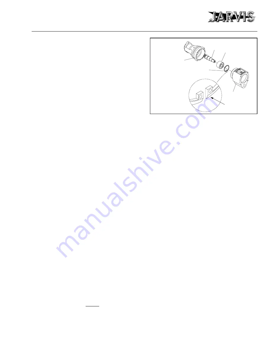
9.1.2 Make sure bevel end of retaining ring (item
34) is facing toward air motor housing
when installed into planetary housing (item
45).
See Figure 6.
AIR MOTOR
HOUSING
ROTOR
NOTE BEVEL
DIRECTION
RETAINING RING
Figure 6
GEAR HOUSING
BALL BEARING
10 MOTOR HOUSING DISASSEMBLY:
10.1 Remove cheese head screws (item 77) and lock
washers (item 76).
10.2 Separate the motor housing assembly and rear
handle assembly as a complete unit from plane-
tary housing assembly.
10.3 Separate the motor housing assembly from rear
handle assembly.
10.4 Slide motor housing assembly (items 62--69, 98
and 99) from motor housing (item 60).
For ease
of removal and installation, use a heat gun to ap-
ply heat to motor housing, if necessary.
10.5 Remove rotor screw (item 69). Use 12 mm
wrench on flats on rotor to prevent rotor from
turning.
10.6 Lift off rear motor plate (item 98) and ball bear-
ing (item 62) from air motor sleeve (item 68).
Use a drive punch if necessary. See note below.
10.6.1 Place drive punch in hole of rotor shaft and
lightly tap until rear motor plate and ball
bearing is free from rotor shaft.
10.7 Slide rotor and bearing assembly (items 62--67)
from air motor sleeve (item 68).
10.8 Remove dowel pins (item 99) if necessary.
10.9 Remove vanes (item 66).
10.10 Press ball bearing (item 62) from splined end of
rotor (item 65). Remove wave spring (item 63).
10.11 Remove o--ring (item 59) from motor housing
(item 60).
10.12 Clean and inspect all parts for wear and replace
as necessary.


