operation and
maintenance instructions
Model SHC 140, 165, 165B, 165G, 165GT and 205
page 16 of 20
PRODUCTS CORPORATION
33 ANDERSON ROAD, MIDDLETOWN, CONNECTICUT 06457-4926
UNITED STATES OF AMERICA E--MAIL.
sales@jarvisproducts.com
TEL. 860-347-7271
FAX. 860-347-6978
WWW.
jarvisproducts.com
JARVIS
6207016::::.
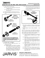
3.3 When the desired length of cut is reached, re-
lease the trigger. This will stop the blade from
rotating.
Continue holding the tool with two hands un-
til the saw blade comes to a complete stop.
3.4 Withdraw the saw blade from the carcass.
Note: Avoid banging the blade into bone, as this could
damage the saw due to the cutting power available. All
cuts should be made in a firm, steady motion with the car-
cass supported to prevent it from moving with the pres-
sure of the blade.
MAINTENANCE INSTRUCTIONS
ALWAYS DISCONNECT ALL HYDRAULIC AND AIR
HOSES AND SHUT OFF THE POWER SUPPLY IN AC-
CORDANCE WITH OSHA’S LOCKOUT/TAGOUT PRO-
CEDURES (29 CFR 1910.147) BEFORE PERFORMING
ANY REPAIRS OR MAINTENANCE
.
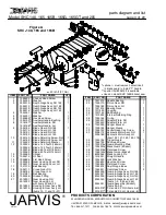
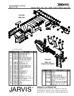
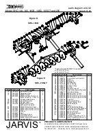
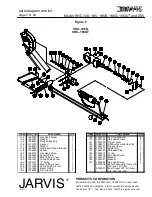
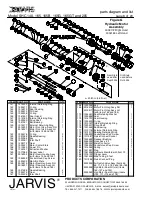
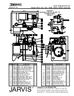
Refer to Figures A to G on pages 4--8 for referenced
items.
1 DAILY:
Note: The hydraulic and air hoses must be
connected and the power turned on to per-
form the above maintenance check only
.
For Single Trigger Tools:
1.1 Make sure that the trigger lever (item 188) is
working correctly. Depress the trigger and the
tool should start. Release the trigger and the tool
should stop.
If the tool malfunctions, repair or
remove it from service immediately
.
For Dual Trigger Tools:
1.2 Make sure that the dual anti--tie down control
triggers on the side and rear handles are working
correctly.
Depress
each trigger separately and
the tool should not start.
Depress
one trigger,
then pause one second and depress the other trig-
ger and the tool should not start. Repeat this pro-
cedure reversing the triggers.
Depress
both trig-
gers simultaneously (within one half second of
each other) and the tool should start. With the
tool running,
release
one trigger and the tool
should stop. Continue holding the depressed
trigger and then depress the other trigger. The
tool should not start.
Repeat
this procedure
holding the other trigger.
If the tool malfunc-
tions, remove it from service and report the
problem to your supervisor immediately
.
Always use two hands when starting and
stopping the tool. Continue holding the tool
with two hands until the saw blade comes to
a complete stop.
1.3 Four (4) times per day, add
Jarvis
1315 White
Grease
to the grease fitting (item 20 or 96) in the
gear housing (item 21, 50 or 99).
1.4 Check the level of the hydraulic fluid in the pow-
er unit.
1.5 Inspect all hoses for leaks, cuts and abrasions
and replace if necessary.
1.6 Check all fittings for leaks and tighten or re-
place, as necessary.
2 WEEKLY:
2.1 Check the condition of the fluid in the hydraulic
power unit. Replace the fluid if it appears dirty
or smells burnt.
Always replace the filters
(items 10 and 15, Figure H, page 9) when chang-
ing the fluid.
3 BLADE REMOVAL:
SHC--140, 165, 165B and 205 Models
3.1 Loosen or remove (SHC--165B) flat head
screws (item 44 or 55) and pivot the blade guard
and gage assembly (item 9, 37 or 48) up and
away from the blade.
3.2 Remove the blade retaining screw (item 10) and
blade retaining washer (item 11) and remove
blade (item 12 or 49).
3.2.1 Place blade locking pin (item 40) through
the hole in the blade to prevent it from rotat-
ing.
3.3 Inspect all parts for wear and replace, as neces-
sary.
3.3.1 Sharpen or replace the blade, as necessary.
SHC--165G Model
3.4 Remove hex head screws (item 79) and separate
cover assembly (items 75--81, 103 and 104)
from blade guard (item 88).
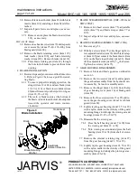
3.5 Remove the blade retaining screw (item 82) us-
ing adjustable spanner wrench (8039093).

