maintenance instructions
Model SHC 140, 165, 165B, 165G, 165GT and 205
page 18 of 20
PRODUCTS CORPORATION
33 ANDERSON ROAD, MIDDLETOWN, CONNECTICUT 06457-4926
UNITED STATES OF AMERICA E--MAIL.
sales@jarvisproducts.com
TEL. 860-347-7271
FAX. 860-347-6978
WWW.
jarvisproducts.com
JARVIS
6207016::::.
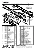
7.9 Disassemble the pinion gear.
7.9.1 Press the ball bearing (item 26) from the
coupling (item 25).
7.9.2 Press the coupling (item 25) from the pinion
gear (item 23).
7.10 Remove bearing race (item 24), if necessary.
7.11 Inspect all parts for wear and replace as neces-
sary.
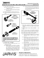
Figure 4
Special Tools
8039139
Needle Bearing
Extraction Tool
8039140 or
8039152
Needle Bearing
Extraction and
Installation Tool
8039118
Needle Bearing
Extraction Tool
THE ABOVE TOOLS ARE RECOMMENDED FOR
PROPER AND EFFECTIVE ASSEMBLY AND DIS-
ASSEMBLY OF THE JARVIS MODEL SHC 140, 165,
165B, 165G AND 205 HYDRAULIC CIRCULAR
SAWS.
8039163 Complete
Tool Kit
8 GEAR HOUSING ASSEMBLY:
8.1 Reverse procedure outlined in section 7.
See
special notes below.
8.1.1
Jarvis
assembly tool 8039152 is available
for the installation of needle bearing (item
22).
See Figure 4.
Always press on the lip
that has the manufacturer’s markings.
Note:
Pressing the unmarked (and unhardened)
lip will deform and damage the bearing.
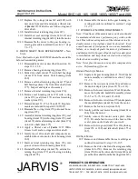
8.1.2 When installing internal retaining ring (item
27), make sure that the beveled edge faces
away from gear housing (item 21, 50 or 99).
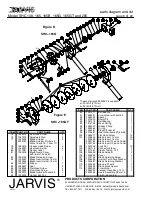
See Figure 5 below.
Retaining
Ring
Gear Housing
Note Bevel
Direction
Figure 5
Retaining Ring
Installation
9 Remember to install wave spring (item 95) in gear
head (item 99) before crown gear assembly (items
90--94).
10 DRIVE SHAFT SEAL REPLACEMENT -- Old
Style:
Note: It is not necessary to disassemble the hydraulic
motor to replace the old style drive shaft seal. All compo-
nents of shaft seal cartridge (items 142--147) must be re-
placed with hydraulic motor seal kit, 3035058.
10.1 Separate the gear housing (item 21, 50 or 99) and
motor assembly as outlined in section 7, steps
7.1--7.3.
10.2 Remove the two screws (item 32) and remove
motor adapter plate (item 29, 52 or 121).
10.3 Remove the internal retaining ring (item 141)
and use the lip on the seal housing (item 143) to
gently lift the seal cartridge (item 142--147)
from the motor.
10.4 Inspect the drive shaft (item 148) for wear or
galling. If the shaft is only polished, proceed to
step 10.5. If shaft needs replacing, refer to sec-
tions 11 and 12.
10.5 Remove the internal retaining ring (item 147).
10.6 Lubricate the new seal (item 144) with
Jarvis
1315 White Grease
and install it in new seal
gland (item 146).

