15
OPERATION—TIG
Before starting any welding activity ensure that you have suitable eye protection and
protective clothing. Also take the necessary steps to protect any persons within the welding
area.
TIG welding mode
Terms used: TIG –
Tungsten Inert Gas, GTAW –
Gas Tungsten Arc Welding.
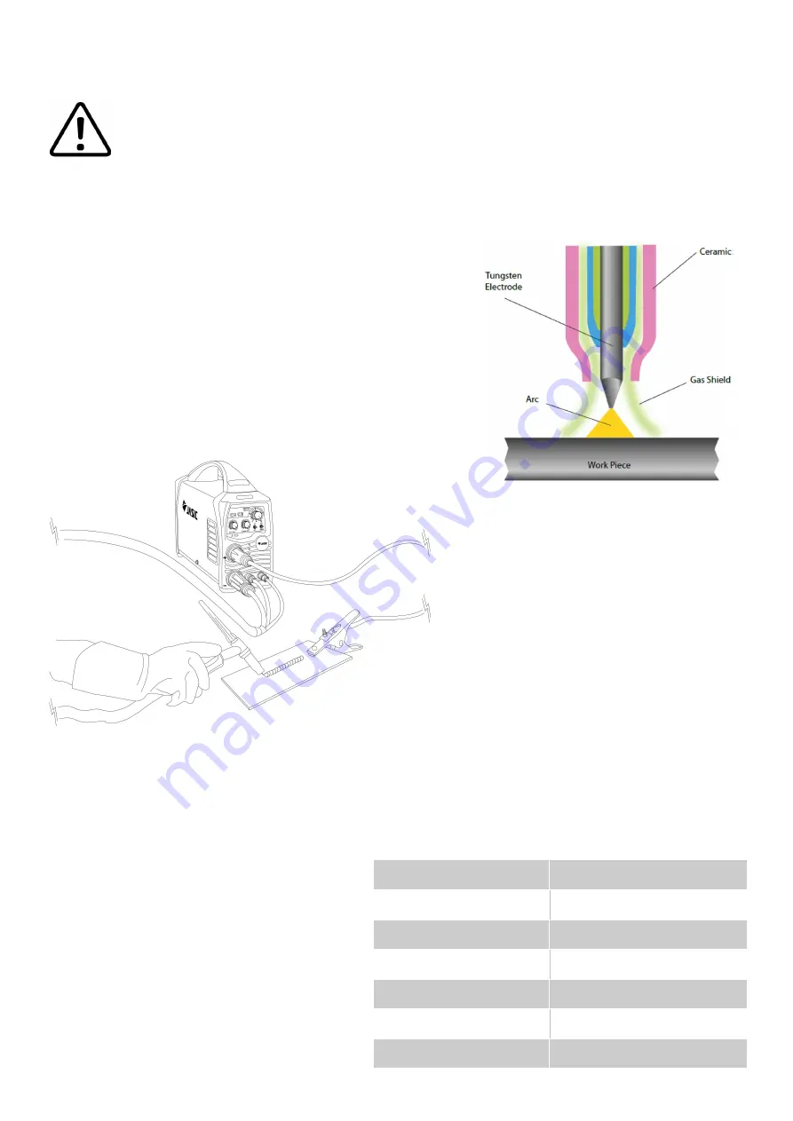
TIG welding is an arc welding process that uses a non
-
consumable
tungsten electrode to produce the heat for welding.
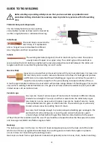
The weld area is protected from atmospheric contamination by a
shielding gas (usually an inert gas such as argon or helium) and a
filler rod matching the base material is normally used, though
some welds, known as autogenous welds, are carried out without
the need for filler wire.
TIG Process can be either DC or AC modes:
DC
-
Direct current for welding steel, stainless steel, copper etc.
AC
-
Alternating current for welding aluminium and it
’
s alloys.
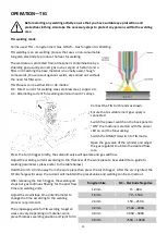
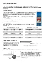
Connect the TIG torch leads as shown.
Ensure that a suitable inert gas supply is
connected.
Switch the power switch on the back panel to
“
ON
”
the machine is started with the power
LED on and the fan working.
Switch the MMA/TIG switch to TIG mode.
Open the gas valve of the cylinder and adjust
the gas regulator to obtain the desired flow
rate.
Press the torch trigger briefly, the solenoid valve will operate and gas will flow.
Adjust the welding current according to the thickness of the work piece to be welded (for a guide to
welding parameters, please refer to the table below).
Hold the torch 2
-
4mm away from the work piece then press the torch trigger. After the arc is ignited, the
HF discharge will cease, the current will maintain the preset value and welding can be carried out.
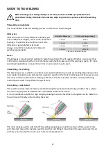
After releasing the torch trigger, the welding arc
stops but gas continues flowing for the post flow
time and welding ends.
Adjust the downslope time potentiometer to
change the time according to the welding
process requirements.
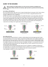
The amperage guide for TIG welding tungsten
sizes can vary depending on material, work
piece thickness, welding position and joint form.
Tungsten Size
DC –
Electrode Negative
1.0mm
15
–
80A
1.6mm
70
–
150A
2.4mm
150
–
250A
3.2mm
250A –
400A
4.0mm
400A –
500A
6.0mm
750A –
1000A


