Page 39
7.3.8 Use of wired welding torch
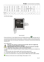
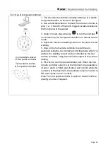
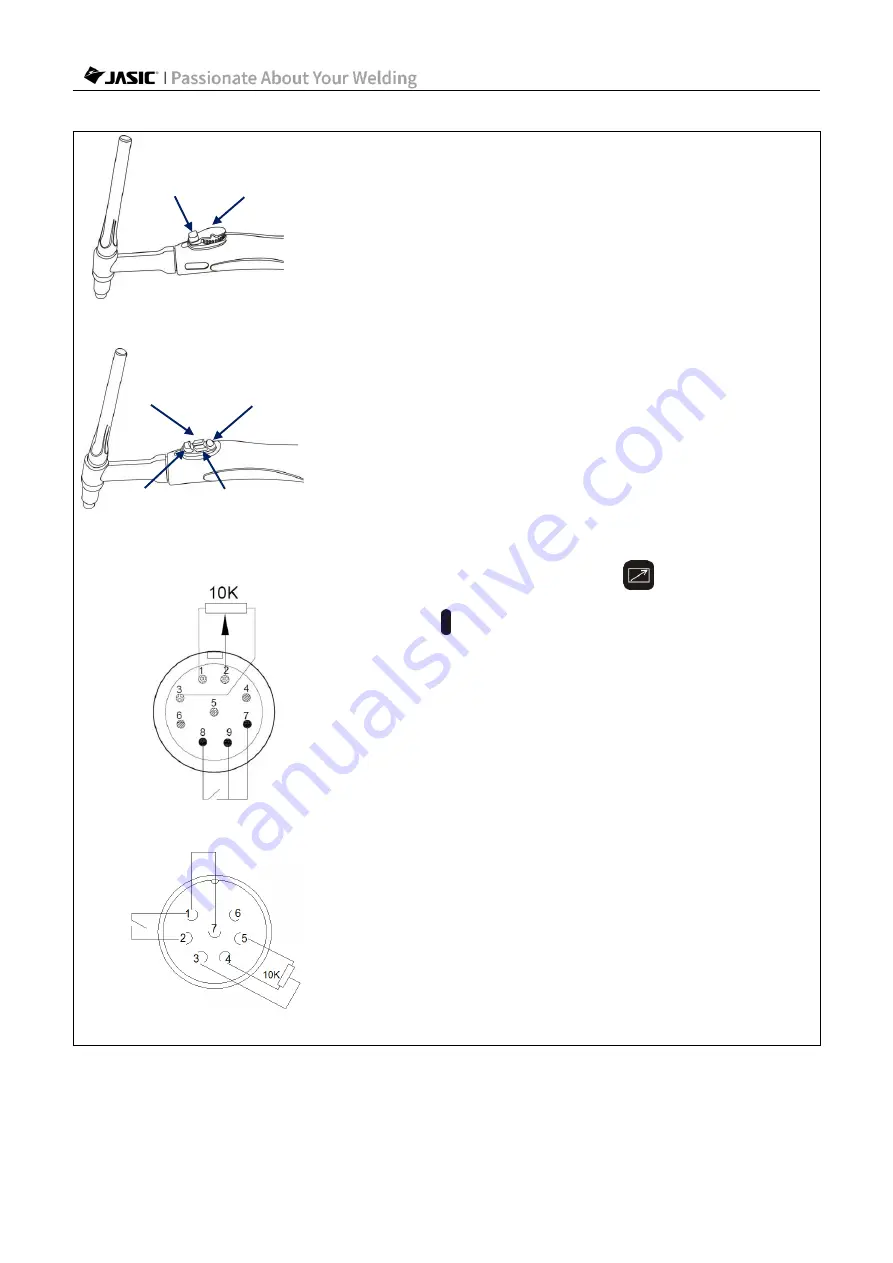
9-pin aviation socket of analog torch
7-pin aviation socket of analog torch
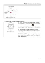
1. Wired welding torch include digital and analog types,
as shown in the following figure.
2. Use a dedicated cable to connect the analog welding
torch to pins 1, 2, 3, 8 and 9 of the torch trigger's aviation
socket on the front panel of the welder; connect pin 7 of
the torch to pin 9.
Pin 2 is the common potentiometer port. When the torch
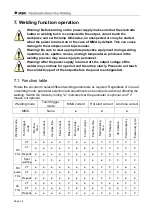
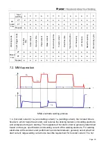
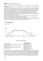
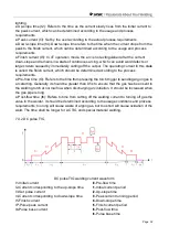
control value is 0 and the current value is at the
minimum, the resistance of pins 1 and 2 is 10kΩ, and of
pins 2 and 3 is 0Ω; when the roller value is at the
maximum and the current value is at the maximum, the
resistance of pins 1 and 2 is 0Ω, and of pins 2 and 3 is
10kΩ.
3. Use a dedicated cable to connect the digital welding
torch to pins 4, 5, 6, 8 and 9 of the torch trigger's aviation
socket on the front panel of the welder. Pin 4 decreases
the value, pin 5 increases the value, and pin 6 is 2T/4T.
Pin 7 of the digital torch is reserved.
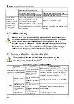
4. Under no load, press the key
to turn on the
indicator . At this time, the welding torch is in torch
control mode.
5. When using the analog welding torch, set the welding
parameters on the panel to start welding. During
welding, the potentiometer can be used to adjust the
welding current from the minimum to the set value.
6. When using the digital welding torch, the Parameter
Selection key on the torch can be used to switch the
adjustment parameter; Parameter Increase and
Parameter Decrease can be used to adjust the
parameter value; and Torch Trigger on the welding torch
can be used to control the output mode.
6.1 Wiring method:
Torch trigger: Pins 8-9; +: Pins 5-9; -: Pins 4-9
Functional parameter selection: Pins 6-9 (Pin 9 is GND)
Note: The analog and digital welding torches are
optional. Specify before placing an order if required.
Torch
trigger
Current
adjustment
potentiometer
Analog welding gun
Parameter
increase
Parameter
selection
Torch
trigger
Parameter
decrease
Digital welding gun

