background image


Page  43 

disassembly and assembly 

The argon gas is impure 

Replace with qualified argon gas 

The gas flow is too large or small 

Adjust the gas flow properly 

Arc is started 
between the 
electrode holder 
and tungsten 
electrode or 
welding torch 

The collet and tungsten electrode 
have poor contact, or arc is 
started when the tungsten 
electrode contacts the base metal 

Replace the collect or repair 

The collet and welding torch have 
poor contact 

Connect the collect and welding torch 
properly 


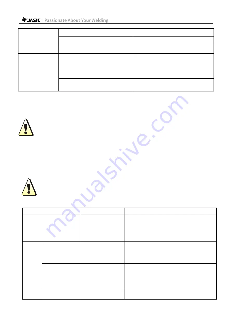
9. Troubleshooting   

Warning! Before arc welding machines are dispatched from the factory, they 
have already been checked thoroughly. The machine should not be tampered 
with or altered. Maintenance must be carried out carefully. If any wire 
becomes loose or is misplaced, it may be potentially dangerous to user! Only 
professional maintenance personnel should repair the machine!   
Ensure the power is disconnected before working on the machine. Always 
wait 5 minutes after power switch off before removing the panels.   


9.1. Common malfunction analysis and solution   

The symptoms listed here may be related to the accessories, gas, 
environmental factors, and power supply you use. Please try to improve the 
environment and avoid such situations.


Elimination of general problems in MMA   

Symptom 

Reasons 

Troubleshooting 

After startup, the fan does 
not turn or the wire feeding 
speed is abnormal 

The air temperature 
may be too low or 
the fan may be 
damaged 

When the temperature is too low, leave the 
machine work for a while. The temperature 
in standby will rise, then fan will resume 
normal operation. If it is still not working, it is 
necessary to replace the fan. 

MMA 

Hard to start the 
arc 

Arc hot start current 
is low 
Or the hot start time 
is short   

Increase arc start current or arc start time   

Unstable arc or 
excessive molten 
pool during arc 
start   

Arc start current is 
high 
Or the arc start time 
is long 

Reduce arc start current or start time 
appropriately 

Cannot start 

The power cord is 
not connected 

Connect the power cord 

Summary of Contents for TIG200PACDC PFC

Page 1: ...Copyright 2022 Shenzhen JASIC Technology Co Ltd TIG200PACDC PFC TIG200PACDC IGBT INVERTER WELDER ...

Page 2: ...o relevant domestic and international standards and that this product conforms to EN60974 1 International Safety Standard Patents protect the relevant design scheme and manufacturing technology adopted in this product 1 Whilst every effort has been made to ensure that the information contained within this manual is complete and accurate no liability can be accepted for any errors or omissions Plea...

Page 3: ...igital panel 19 6 2 Function table of plastic display panel 19 6 3 Use of remote controller 23 6 4 Other functions 25 7 Welding function operation 29 7 1 Function table 29 7 2 MMA operation 30 7 3 TIG operation 31 8 Maintenance 41 8 1 Power supply maintenance 41 8 2 Welding torch maintenance 41 9 Troubleshooting 43 9 1 Common malfunction analysis and solution 43 9 2 Alarm and solutions 45 10 Packa...

Page 4: ...safety please read this manual carefully before installing and operating this JASIC equipment Pay extra attention to all content marked with All operations must be carried out by professional suitably qualified persons ...

Page 5: ...he machine Electric shock May cause serious injury or even death The equipment should be installed by a qualified person and in accordance with current standards in operation It is the user s responsibility to ensure that the equipment is connected to a suitable power supply Consult with your utility supplier if required Do not use the equipment with the covers removed Do not touch live electrical...

Page 6: ... material to cool before touching it or placing it in contact with combustible or flammable material Do not work in atmospheres with high concentrations of combustible fumes flammable gases and dust Always check the work area half an hour after cutting to make sure that no fires have begun Take care to avoid accidental contact of electrode to metal objects This could cause arcs explosion overheati...

Page 7: ...first disconnecting the power supply cable Replace the coverings and protections and close all doors when the intervention is finished and before starting the equipment Take care to avoid getting fingers trapped when loading and feeding wire during set up and operation When feeding wire be careful to avoid pointing it at other people or towards your body Always ensure machine covers and protective...

Page 8: ...y with the panels removed 1 When the operator s movement is limited by the surroundings for example the operator can only bend his knees barefoot or lie down during operation the operator shall practice proper insulation and avoid direct contact with conductive parts on the equipment 2 Do not use the welder in closed containers in narrow spaces where conductive components cannot be removed 3 Do no...

Page 9: ...on indicator Lift TIG mode Warning tag Wireless remote control indicator MMA mode Pairing of minimalist wireless remote controller optional MMA current Remote control key Hot start current of MMA Smart gas Arc force of MMA Water cooler function Other function switching Parameter adjustment and confirmation key Welding mode switching DC mode HF arc starting mode Pulse mode ...

Page 10: ... welder Dynamic LED display of operating state Immediately displays the current operating state Anti stick function Prevents the welding electrode from sticking to the workpiece during welding VRD function Protects the operator from high voltage electric shock when the machine is not working MMA hot start function Makes MMA arc starting easier and more reliable Smart fan control Prolongs the lifes...

Page 11: ...30V 10 160 115V 10 120 10 160 Rated working voltage AC230V V 18 TIG 26 4 MMA 18 TIG 26 4 MMA Rated working voltage AC115V V 16 4 TIG 14 8 MMA Arc force current range A 0 40 0 40 Hot start current range A 0 80 0 80 No load voltage V 65 60 VRD voltage V 11 5 11 5 AC output frequency Hz 20 250 20 250 AC balance 20 60 20 60 Base current A 5 200 5 200 Pulse frequency DC Hz 0 5 200 0 5 200 Pulse frequen...

Page 12: ...ng and lift arc starting Duty cycle TIG 25 MMA 30 TIG 25 MMA 20 Efficiency 80 80 Power factor 0 95 0 75 Insulation class H H Protection class IP23S IP23S Dimensions L W H mm 490 165 341 490 165 341 Dimensions of package L W H mm 735 230 440 735 230 440 Net weight Kg 11 8 11 7 Overall total weight Kg 16 8 16 8 Characteristics CC CC Pollution level Grade 3 Grade 3 ...

Page 13: ...t Warning This product meets the requirements of Class A equipment in EMC requirements and is not to be connected to a residential low voltage power supply grid 5 1 External interface description Front panel view Rear panel view a Power switch b Input power cord c Inlet nozzle d Water cooler socket plus version only e Negative polarity f TIG welding torch gas connector g Positive polarity h 9 pin ...

Page 14: ...wrong grade 2 Ensure that the input power cable is in good contact with the power terminal or socket 3 Ensure the input voltage value is within the specified input voltage range 4 Ground the power supply well As shown in the diagram the European plug has a grounding terminal so no additional grounding is required 5 Ensure that the power switch of the welder itself is turned off Wiring diagram NOTE...

Page 15: ...rode Generally speaking DCEP is recommended for basic electrodes i e electrode connected to the positive polarity while no special provisions are made for acid electrodes 1 Ensure that the power switch of the welder is turned off 2 Insert the cable plug with electrode holder into the corresponding socket on the front panel of the welder and tighten it clockwise 3 Insert the cable plug with earth c...

Page 16: ...e welding torch into the gas outlet on the front panel 5 Connect the gas hose of the argon cylinder to the inlet nozzle on the rear panel of the machine Wiring diagram NOTE If you want to use long secondary cables TIG torch cable and earth cable you must ensure that the cross sectional area of the cable is increased appropriately in order to reduce the voltage drop due to the cable length 6 In AC ...

Page 17: ...up refer to the following good practices Bad practice Good practice Do not wind up the excessive cable along the same direction Wind up the same number of turns in the cable winding direction and the opposite direction and stack them together ...

Page 18: ...emote controller before installation 5 6 Installation of wireless receiver module optional Installation drawing Remove the plug shown in above left figure and refit into the space the wireless receiver module shown in above right figure 1 Remove the screws on the left cover of the machine 2 Remove the buckle inside the front panel of the machine and pull out the plug 3 Insert the wireless receiver...

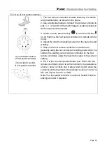
Page 19: ...lastic display panel a Enable remote control 1 Before welding press the remote control function key to enable the remote control function 2 If the indicator is on it indicates that the remote control function is enabled If the remote controller is connected the remote controller controls the welding current If no remote controller is not connected the welding current is controlled by the panel adj...

Page 20: ...when it is switched to frequency d Smart gas If the indicator is on it indicates that the machine is in Smart gas mode This function automatically matches the appropriate post flow time according to the user s welding specifications which can effectively save the amount of argon e Water cooler control plus version only 1 Press the water cooler control key to enable or disable water cooled mode 2 I...

Page 21: ...ten anode time to the AC cycle Duty ratio indicator When the indicator is on it indicates the ratio of peak current time to pulse period Pulse frequency indicator When the indicator is on it indicates the pulse frequency Spot welding time indicator When the indicator is on it indicates the spot welding time Mixed frequency indicator When the indicator is on it indicates the mixed AC frequency Mixe...

Page 22: ...ne is in 2T mode 2 4T indicator When the indicator is on it indicates that the machine is in 4T mode 3 Repeat mode indicator When the indicator is on it indicates that the machine is in cycle mode 4 Spot welding indicator When the indicator is on it indicates that the machine is in spot welding mode Press the pulse selection key to switch between pulse and no pulse 1 No pulse indicator When the in...

Page 23: ...ves have less arc noise and are softer 1 Press the MMA parameter key to switch the function 2 Welding current indicator When the indicator is on it indicates that the MMA welding current has been selected 3 Hot start indicator When the indicator is on it indicates that MMA hot start current has been selected 4 Arc force current indicator When the indicator is on it indicates that the MMA arc force...

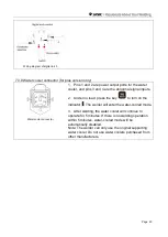
Page 24: ...ator will turn on insert the aviation plug of the wired remote controller into the aviation socket to adjust the welding current through the remote controller 6 3 3 Optional remote control models Type Name Model Host receiver module Welding mode Picture Wired Analog torch trigger 10K potentiometer Analog welding torch None TIG Digital torch trigger Digital welding torch None TIG Wired foot remote ...

Page 25: ... correspond to the response time in minutes The default value is 10 3 After adjusting the standby response time press the Current Setting Encoder key to save the current settings 4 Press the welding mode key to complete the operation and exit 5 The standby function is only available in TIG mode If the machine is not used within the set response time it will enter standby state and only the middle ...

Page 26: ...ockwise 0 not enabled 1 enabled 3 After adjusting the standby response time press the Current Setting Encoder key to save the current settings 4 Press the welding mode key to complete the operation and exit The standard machine only supports overvoltage protection function and this function is enabled by default 6 4 3 Restore factory settings Press and hold the welding mode key for 5s to restore f...

Page 27: ...urrent A Arc force current A DC TIG 0 5 20 0 5 100 0 5 20 2 1 DC pulse TIG 0 5 20 0 5 100 50 0 5 20 2 50 50 MMA 100 30 30 Welding mode Pre flow time s Initial current A Up slope time s Peak current A Base current A Down slope time s Finish current A Post flow time s Spot welding time s Pulse frequency Hz Duty cycle AC frequency Hz AC balance AC TIG 0 5 20 0 5 100 0 5 20 2 1 20 20 AC pulse TIG 0 5 ...

Page 28: ...ration on the panel the barcode automatically exits after 20s 6 4 5 VRD function Warning The electrical connection of the machine must be completed by electricians with qualification certificates Warning Electric shock may cause death after power failure the machine will still have high voltage so do not touch the live parts The MMA VRD mode is enabled by default in factory settings and the user c...

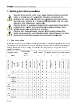
Page 29: ...ay continue for a period and then drop slowly Please do not touch the conductive part of the output before the panel is extinguished 7 1 Function table Rotate the encoder to select different welding parameters as required Regardless of no load or welding mode parameter selection and adjustment can be carried out without affecting the welding Switch the mode by rolling indicates that the parameter ...

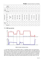
Page 30: ...Ih hot start current IΔh arc starting current Ia welding current the hot start time is fixed at th which helps the arc start and reduces the sticking tendency of welding electrode and workpiece during arc starting The magnitude of hot start current is generally determined based on the type specification and welding current of the welding electrode For welding electrodes with sound arc start perfor...

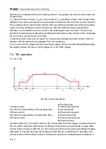
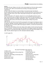
Page 31: ...e electrode is separated from the workpiece 4 U0 is open circuit voltage and Uw is working voltage When not performing MMA welding the welder outputs the open circuit voltage U0 or the VRD voltage 7 3 TIG operation 7 3 1 DC TIG DC TIG current waveform t0 Pre flow time I1 Initial current t1 Initial current period I2 Current corresponding to the up slope time t2 Up slope time I3 Peak current t3 Peak...

Page 32: ...s to the time from pressing the torch trigger to sending argon gas to arc starting Generally it should be greater than 0 5s to ensure that the gas has been sent to the welding torch at normal flow when discharging arc initiation It should be increased when the gas pipe is long Post flow time t6 Refers to time from cutting off the welding current to turning off gas the valve in the welder It should...

Page 33: ...IG AC TIG welding current waveform I1 Initial current t2 Up slope time I3 Set AC peak current t4 Down slope time I5 Finish current tc Cleaning current time T AC period AC TIG supports square triangular and sine output waveforms AC and DC TIG have the same pre flow time and post flow time but the other parameters are explained separately in conjunction with the figure Initial current I1 peak curren...

Page 34: ...s Duty cycle 100 tp Tp Can be adjusted according to process requirements AC balance 100 tc Tc Can be adjusted according to process requirements AC pulse TIG welding supports square triangular and sine output waveforms AC pulse TIG welding is basically the same as AC square wave TIG welding but its welding current is controlled by a low frequency pulse and therefore changes with the pulse value to ...

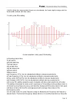
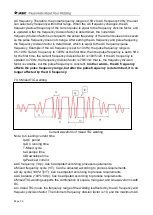
Page 35: ...If the AC frequency is updated to 70Hz the frequency division factor is 70 5 14 that is the frequency division factor is variable but the pulse frequency is constant In other words the AC frequency affects the pulse frequency range but after the pulse frequency is determined it is no longer affected by the AC frequency 7 3 5 Mixed TIG welding Current waveform of mixed TIG welding Note tc Cleaning ...

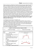
Page 36: ...ant In other words the AC frequency affects the frequency range of mixed TIG welding but after the mixed TIG frequency is determined it is no longer affected by the AC frequency 7 3 6 Welding mode description of TIG welding torch TIG operation mode has a special convention which specifies the mode or method of controlling the welding current change by different operations of torch trigger during T...

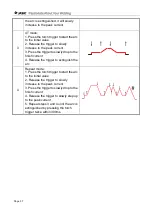
Page 37: ...slowly drop to the finish current 4 Release the trigger to extinguish the arc 4 Repeat mode 1 Press the torch trigger to start the arc to the initial value 2 Release the trigger to slowly increase to the peak current 3 Press the trigger to slowly drop to the finish current 4 Release the trigger to slowly step up to the peak current 5 Repeat steps 3 and 4 until the arc is extinguished by pressing t...

Page 38: ... Step on the foot remote controller to start the arc generally using the non contact arc starting mode After it is started the welding current will be controlled by the foot remote controller using the maximum output of the current setting 6 Pin 2 is the common potentiometer port When the foot remote controller current is at the minimum the resistance of pins 1 and 2 is 10kΩ and of pins 2 and 3 is...

Page 39: ... decreases the value pin 5 increases the value and pin 6 is 2T 4T Pin 7 of the digital torch is reserved 4 Under no load press the key to turn on the indicator At this time the welding torch is in torch control mode 5 When using the analog welding torch set the welding parameters on the panel to start welding During welding the potentiometer can be used to adjust the welding current from the minim...

Page 40: ...signal inputs 2 Under no load press the key to turn on the indicator The welder will enter the water cooled mode 3 After welding the water cooler will continue to operate for 5 minutes If there is no welding operation within 5 minutes water cooled mode will be automatically disabled Note The welder can only use the original supporting water cooler Do not use water coolers purchased from other manu...

Page 41: ...the condition of the machine mains cables welding cables and connections Check for any warnings LEDs and machine operation Monthly examination Disconnect from the mains supply and wait for at least 5 minutes before removing the cover Check internal connections and tighten if required Clean the inside of the machine with a soft brush and vacuum cleaner Take care not to remove any cables or cause da...

Page 42: ...en the welding torch and the water inlet pipe is leaking Open it to repair the welding Air leakage The sealing ring has aged Replace the sealing ring The connecting thread is loose Tighten it The gas inlet pipe joint is damaged or not fastened Cut off the damaged joint reconnect and tighten the replaced gas intake pipe or reliably wrap the damaged area The gas inlet pipe has been damaged by heat o...

Page 43: ...ore working on the machine Always wait 5 minutes after power switch off before removing the panels 9 1 Common malfunction analysis and solution The symptoms listed here may be related to the accessories gas environmental factors and power supply you use Please try to improve the environment and avoid such situations Elimination of general problems in MMA Symptom Reasons Troubleshooting After start...

Page 44: ...current is output when torch switch is pressed Some TIG modes allow welding to end when the switch is pressed Release the torch switch and start over Welding circuit is blocked Check the welding circuit and reconnect it No discharge after pressing the torch switch to start the arc when starting the arc at high frequency The torch switch is not plugged in Plug in the torch switch Excessive spark ga...

Page 45: ...connect equipment that could seriously interfere with welder Other faults Please contact the maintenance personnel of JASIC Technology Co Ltd 9 2 Alarm and solutions Error code Category Possible cause Countermeasure E10 Overcurrent protection Continuously output the maximum capacity current of welder Restart the welder If overcurrent protection alarm is still active contact the after sales departm...

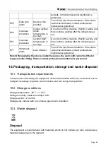
Page 46: ...t If the alarm cannot be eliminated contact professional maintenance personnel Note After applying the above countermeasures the alarm still cannot be lifted or reappears after lifting Please contact professional maintenance personnel 10 Packaging transportation storage and waste disposal 10 1 Transportation requirements In the process of handling the equipment it should be handled with care and s...

Page 47: ...nmentally compatible recycling facility In order to comply with WEEE regulations in your country you should contact your supplier RoHS compliance declaration We herewith confirm that the above mentioned product does not contain any of the restricted substances as listed in EU Directive 2011 65 EC in concentrations above the limits as specified therein Disclaimer Please note that this confirmation ...

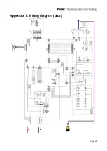
Page 48: ...Page 48 Appendix 1 Wiring diagram plus ...

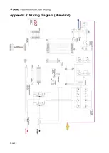
Page 49: ...Page 49 Appendix 2 Wiring diagram standard ...

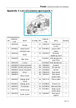
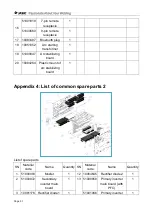
Page 50: ... 51000820 Main transformer 1 6 10084066 Front panel bracket 1 25 10084383 Chassis 1 7 51000881 Small control panel 1 26 10084196 Fan bracket 1 8 10084430 Acrylic front panel 1 27 51000956 DC fan 1 9 10083484 Knob 1 28 10084109 Rear panel 1 10 10084650 Silicon button 1 29 10084163 Rear panel support plate 1 11 10084392 Display panel mount 1 30 10071118 Power switch 1 12 51000844 Display panel 1 31 ...

Page 51: ...d 1 20 10084264 Plastic mount of arc stabilizing board 1 Appendix 4 List of common spare parts 2 List of spare parts SN Material code Name Quantity SN Material code Name Quantity 1 51000093 Mosfet 1 12 10064645 Rectifier diode 2 1 2 51000872 Secondary inverter main board 1 13 51000858 Primary inverter main board with PFC 1 3 10081176 Rectifier diode 1 1 51001066 Primary inverter 1 ...

Page 52: ... PFC 1 5 10084373 Current sensor 1 15 10050418 Heat sink 4 1 6 10084338 Heat sink 1 1 16 10084138 Aluminum connector 1 7 51000796 Thermal resistor 1 17 51000852 Heat sink 5 1 8 10084197 Inverter wind shield 1 9 10084337 Heat sink 2 1 10 10084340 Heat sink 3 1 11 51000601 IGBT 1 ...

Reviews: