background image

Jason International, Inc.  •  


501.771.4477  


Page 7 of 16


Customer Service :  800.255.5766 

Copyright © 2011 Jason International.

INSTALLATION INSTRUCTIONS (cont.)

ELECTRICAL

electrical  Power  Supply:   

These  instructions  are  written 

assuming 60Hz, 120v power supply.  Special notations are 
also included for the Export versions of the control equipment, 
and power supply.

WA R N I N G

:  

V e R I F I cAT I O N   O F   e L e c T R I cA L 

R e q u I R e m e N T S   m u S T   B e   m A D e   B e F O R e 

INSTALLATION.  ReFeR  TO  The  equIPmeNT  LABeLS 

FOR VOLTAGe AND FRequeNcy RequIRemeNTS.

NOTe: Verify that the electrical service matches either the 

120v (or 240v for Signature edition) system requirements 

for this bath.

NOTe:  The  bath  is  designed  for  indoor  use  only.  The 

electrical  equipment  must  not  be  exposed  to  direct 

or  indirect  water  or  moisture  contact.  The  electrical 

equipment must also be protected from dust and other 

airborne debris before, during, and after installation.

electrical Service: 

1. 

A licensed electrician must provide 

the  “dedicated”  electrical  service  protected  by  a  GFCI. 
The  location  of  the  GFCI  must  be  at  least  five  (5)  feet 
(152  cm)  away  from  the  inside  surface  of  the  bath, 
accessible for regular testing. Use copper conductors only.


DANGeR  —  RISK  OF  eLecTRIc  ShOcK:  connect 

only to a circuit protected by a Ground Fault circuit 

Interrupter  (GFcI).  In  the  unlikely  occurrence  of 

a  current  imbalance  in  the  power  conductors, 

the  GFcI  will  interrupt  the  power  to  the  bath. 

WARNING:  The  eLecTRIcAL  SeRVIce  TO  The 

GFcI  muST  NOT  Be  INTeRRuPTeD  By  ANy 

cONTROL  DeVIce.  LIKeWISe,  The  eLecTRIcAL 

SeRVIce FROm The GFcI TO The BATh cONTROL 

ShOuLD  Be  DIRecT  AND  NOT  INTeRRuPTeD 

By  A  SWITch.  NeVeR  uSe  A  SWITch  IN 

cONJuNcTION  WITh  A  cONTROL  DeVIce.  ThIS 

WILL  VOID  The  mANuFAcTuReR’S  WARRANTy. 

G R O u N D I N G  

I S  

R e q u I R e D 

2. 

The  unit  should  be  installed  by  a  qualified 

service  representative  and  properly  grounded. 

I N S T A L L   S E R V I C E   C O N N E C T I O N   A T 

3. 

L E A S T   6 ”   (15 c m)   A B O V E   S U B   F L O O R . 
 

ALL LOcAL AND STATe eLecTRIcAL AND PLumBING 

cODeS muST Be OBSeRVeD.

 Where there are no local 

codes the 

National electric code (Nec)

 and

 uniform 

Plumbing  code  (uPc) 

shall  be  observed.  It  is  the 

responsibility of the installer/owner to determine specific 
code compliance prior to installation of the product. 

NOTe:


In the Commonwealth of Massachusetts, installation is to 
be done by a Massachusetts licensed plumber.

Standard/Premier  edition  control  Box  (120v).

4. 

  The 

blower is prewired to the control box. The control box has 
a 36” (91cm) cord with plug end. The blower control box 
is mounted on a stand that is temporarily secured to the 
packing board for shipping. During installation, the control 
box bracket and controls must be positioned horizontally 
and located to permit access for inspection and servicing. 
The blower control box must be plugged into a dedicated 
120v (volt), 15A (amp), 60Hz (hertz), Ground Fault Circuit 
Interrupter (GFCI) protected circuit.  

(See Figure 7)

Standard/Premier  edition  control  Box  (240v).

5. 

  The 

blower  is  prewired  to  the  control  box.  The  control  box 
has  a  36”  [91  cm]  cord  with  a  junction  box  connection. 
The  blower  control  box  is  mounted  on  a  stand  that  is 
temporarily  secured  to  the  packing  board  for  shipping. 
During installation, the control box bracket and controls 
must  be  positioned  horizontally  and  located  to  permit 
access for inspection and servicing. The blower control 
box  must  be  plugged  into  a  dedicated  240v  (volt),  15A 
(amp), 50Hz (hertz), Ground Fault Circuit Interrupter (GFCI) 
protected circuit.  

(See Figure 7)

Signature edition control Box.

6. 

 The blower is prewired to 

the control box. The control box has a 36” (91 cm) cord with a 
junction box connection. The blower control box is mounted 
on a stand that is temporarily secured to the packing board 
for shipping. During installation, the control box bracket 
and controls must be positioned horizontally and located 
to permit access for inspection and servicing. The blower 
junction  box  must  be  connected  into  a  dedicated  240v, 
15A, 50 or 60Hz, GFCI protected circuit.  

(See Figure 7) 

DANGeR:  Do  not  alter  the  factory  installed  wiring.  All 

building materials and wiring should be routed away from 

the  equipment  or  other  heat-producing  components  of 

the unit.

Summary of Contents for AirMasseur Madeline MA635P

Page 1: ... in writing with a request for a representative to inspect the unit Failure of the carrier to respond should be reported to the seller and carrier Always file a freight claim promptly The installer is responsible for insuring that the unit is free from defects or shipping damage In the event of a problem DO NOT install the unit Jason International is not responsible for damage that might have been...

Page 2: ...nd skirt center lines Tape the template to the sub floor in its desired location 6 Markonthesub floor the sump area location the water inlet stub outlocation andtheremoteblower tubingfloorcutout location Two remote blower tubing floor cutout locations and water inlet stub out locations have been indicated on the template Choose the one that is preferable for your installation 7 Removethetemplatean...

Page 3: ...AUTION Only dry fit the drain and overflow tee to the P trap at this time c Disconnect the drain and overflow from the bath and leave the drain assembly free standing in the P trap 12 Align the drain with the centerline on the template See Figure 4 13 Permanently attach the drain tee to the P trap 14 Remove the template from the floor 15 Place the bath skirt into position and attach to the floor b...

Page 4: ... overhang into the well of the bath This will insure an unobstructed water flow out of the faucet when filling the bath Follow the faucet manufacturers installation instructions REMOTE MOUNTING of air blower Do not remote mount the blower and control box more than 15 feet 457 cm away from the air inlet of the bath Choose a location as close as possible to the bath to assure maximum efficiency 1 Th...

Page 5: ...les back up through the floor cutout When installing on a cement slab a conduit may be used if desired to run the cable from the bath to the control box This will allow the bath to be lifted and removed from the skirt if access is required in the future During installation if it is preferred to run the blower hose on top of the floor a 2 1 2 6 35 cm diameter hole can be drilled in the toe kick are...

Page 6: ...f the bath s Level Form Base must be level with the bottom of the skirt Note Do not use a sand bed to install or level the bath 9 Bolts a Startwithone 1 boltandliftthebathenoughtopartially install the bolts Do not tighten the bolts completely at this time Align the bolts with the slot in the bath bracket Repeat the process until all six 6 bolts are partially installed b Continue to fully tighten a...

Page 7: ... CODES MUST BE OBSERVED Where there are no local codes the National Electric Code NEC and Uniform Plumbing Code UPC shall be observed It is the responsibility of the installer owner to determine specific code compliance prior to installation of the product NOTE In the Commonwealth of Massachusetts installation is to be done by a Massachusetts licensed plumber Standard Premier Edition Control Box 1...

Page 8: ... acrylic surface during installation to minimize cleanup and prevent surface damage WATER TESTING Before finishing the installation it is recommended that the bath be water tested and the plumbing tested for leaks Before water testing the bath 1 make sure any pump unions are hand tight Do not over tighten or use a pipe wrench This will damage the unions and cause leaking If the unit leaks with the...

Page 9: ...0v systems the power cord for the Blower control box must be plugged into a 120v 15 amp GFCI dedicated circuit NOTE This diagram Figure 12 also applies to 50 Hz 240v controls and power supply systems Except that the Blower junction box must be connected into one dedicated 240v 15 Amp GFCI circuit NOTE This diagram Figure 13 also applies to 50 Hz 240v controls and power supply systems Except that t...

Page 10: ...d the blower will start again for a two minute purge cycle that dries the air channel Note that the blower light will flash during the 15 minute pause before the purge cycle begins Once the purge cycle begins all indicators will light and the keypad operation will be disabled for two 2 minutes SIGNATURE EDITION AIRMASSEUR The Jason Signature Edition AirMasseur bath includes a variable speed 1 HP a...

Page 11: ...ivating this setting Signature Remote Control In addition to the main control touchpad installed on the bath deck a floating waterproof Universal Remote Control is provided with all Signature Edition AirMasseur baths This remote control provides the same control functions as the bath s main control console plus the bather may remotely operate a TV DVD VCR CD etc Refer to the Instruction Manual pro...

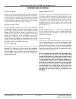
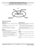
Page 12: ...l LED light if installed Press the icon for less than two 2 seconds to turn the lights Off or On Hold the icon for more than two 2 seconds to change modes This function has a two 2 hour timer and remembers the last mode OPERATING INSTRUCTIONS FEATURES AND CONTROLS cont OPERATING INSTRUCTIONS AirMasseur Icon The AirMasseur icon is used to activate the blower and the 20 minute timer Pressing the Ico...

Page 13: ...NNECTIONS section Remote Control The Signature Edition control system includes a waterproof floatingUniversalRemoteControl Itcontrolsallbathfunctions plus a TV DVD CD etc which can be heard through the optional Sound Immersion Transducers optional Blower On Off Modes Blower Speeds LED Light IR for Remote OPERATING INSTRUCTIONS FEATURES AND CONTROLS cont OPERATING INSTRUCTIONS Blower On Off and Mod...

Page 14: ...erial number proof of purchase andmodelnumber Thiswillinsureaquickresponse on warranty items The serial number can be found on the front page of this manual or on the small card adhered to the back of the bath just above the equipment HUMIDITY Warning Avoid high humidity levels in your home Mold mildew fungi and bacteria which maybeharmfultohealththriveinareaswith continued high humidity levels th...

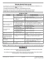
Page 15: ...FCI tripped b Refer to installer dealer Circuit breaker trips repeatedly a Defective breaker a Replace breaker b Short circuit between bath and blower breaker box b Refer to installer dealer c Other items are connected to the same circuit c Refer to installer dealer Blower does not shut off a Defective keypad or timer a Refer to installer dealer Replace keypad or control Air bath does not function...

Page 16: ...h the possibility of drowning Never use the therapy bath while under the influence of alcohol anticoagulants stimulants antihistamines vasoconstrictors vasodilators hypnotics narcotics or tranquilizers F Persons with a medical history of heart disease low or high blood pressure circulatory system problems or diabetes should consult a physician before using a therapy bath G Persons using medication...

Reviews: