Jason International, Inc. •
501.771.4477
Page 12 of 20
Customer Service : 800.255.5766
Copyright © 2018 Jason International, Inc.
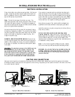
PVC PIPE
LEVELFORM BASE
CONSTRUCTION
ADHESIVE
FINISHED FLOOR
SKIRT
OVERFLOW
COUPLING
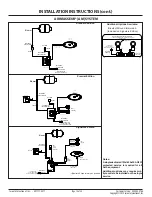
INSTALLATION INSTRUCTIONS (cont.)
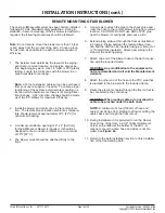
8. Use the template to verify the four (4) locating stud
holes on the bottom of the skirt.
9. After the finished floor is installed,
position the
installation template on the finished floor. Place the
template to line up with the existing floor drain location
and orient the template to the desired position.
Note: The sump area location cutout and remote
blower tubing floor location cutout (when appli-
cable), and water inlet stub-out must line up with
the template.
10. Tape the template to the finished floor;
using care
to align both center lines and assure that the template
is lying flat on the floor.
11. Transfer the center lines of the template to the
finished floor and use the template to locate where
to drill the pilot holes for the four locating studs.
If installing on a wooden floor, 1/4” holes are required
and a 5/16” nut to install the locating studs. When
installing on a cement slab, 3/8” holes are required.
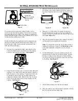
See Figure 3.
CAUTION: Use a marker that can be removed from
the finished floor after installation.
12. Remove the template for the floor.
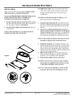
13. Install the locating studs into the four (4) positions on
the floor.
See Figure 3.
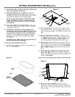
14. Drain and Overflow.
Use the 1-1/2” coupling, which
is pre-attached to the bath and lengthen the overflow
pipe to the desired length. Then attach the drain to the
bath.
15. Remote Mounting of the Blower.
If the blower for
the AirMasseur bath is to be remote mounted, refer to
the
REMOTE MOUNTING OF AIR BLOWER
section
of this manual before proceeding to the next step.
16. Route cables.
When applicable, route any electronic
cables through the floor cutout and make the appropri-
ate connections to the control box. See the
CONTROL
BOX CONNECTIONS
section of this manual for loca-
tions.
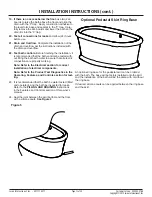
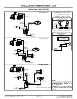
17. Jason baths are designed to be supported at the
base of the bath.
If the floor is smooth and level the
bath’s level form base will provide proper drainage and
support.
See Figure 4
Note: Do not use a sand bed to install or level the bath.
Figure 2
Figure 3
Locating Stud Bolts (x4)
Remote Blower
Tubing Floor
Location
Sump Area
Location
Drain
Overflow
Coupling
Overflow
Floor
"P" Trap
Figure 4
18. Below the floor installation.
Apply construction
adhesive to the level form base if desired. Position the
bath in place. From below the floor, connect the drain
to the ‘P’ trap.


