Jason International, Inc. •
501.771.4477
Page 3 of 9
Customer Service : 800.255.5766
INSTALLATION
See the
USER MAINTENANCE INSTRUCTIONS
section
of this owner’s manual, prior to installation, for humidity and
mold prevention suggestions.
1.
Finish Frame:
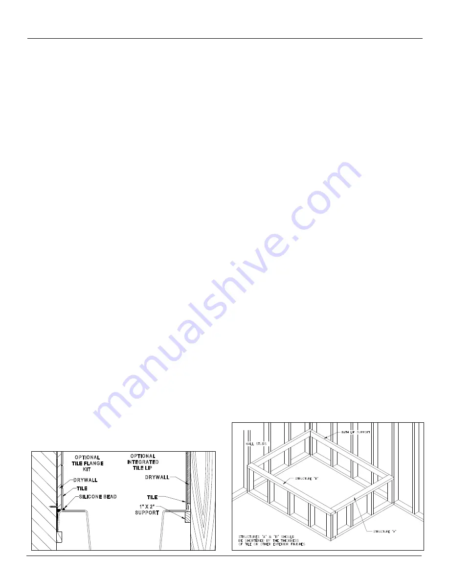
A finish frame under the shell rim should
also always be constructed to support the bath deck and
insure proper drainage toward the bath well. This frame is
not intended to support the full bath weight
(see Figures
1 & 2)
.
Jason offers a removable lateral skirt for most baths.
The skirts are available in matching acrylic colors and
provide convenient access to bath equipment as well as an
excellent finished appearance. However, if Jason’s lateral
skirt is not used, an access panel MUST be provided to
enable final electrical connections and service. Please
refer to the minimum recommended access panel size
in
Table 1 - Specifications.
If a Jason lateral skirt is to be used, the bath deck must
be leveled at 20.5” (52cm) from the support floor or the
skirt will not fit properly.
CAUTION: Make sure the support frame is drilled
and/or notched as needed to assure that the ON/
Off air actuator switch and air tube are not bound
or pinched.
Allow ample clearance for the pump.
Whirlpools with
optional front pump mounts may require a minimum of
1” clearance beyond the front and pump side lip of the
bath to allow clearance of the pump.
CAUTION: Ambient temperature under the bath
where the pump and electronics are installed must
not exceed 122°F (50°C).
2. 100% Silicone with mildew resistant properties should be
applied between the water resistant backer board and
the deck of the bath.
NOTE:
If you use a tile flange kit,
modify the framing to support the bath lip as shown in
Figure 1
.
3. Install the drain and overflow assembly to the bath shell
according to the instructions provided with the drain and
position the bath in the area of intended installation.
4. Finish plumbing rough-in of drain and overflow assembly.
At this time, considerations should be made for the
position and mounting of the faucet set, as well as all
related plumbing.
5.
Remove the packing board before installing the bath.
The bath is equipped with separate bath equipment
support bases which are joined for shipment with packing
boards. Detach the packing board from the bath and from
underneath the equipment.
WARNING: Any modification to the equipment is
not recommended and will void the Manufacturer’s
warranty.
6. I
nstall the bath level for proper drainage.
Jason baths
are designed to be supported at the base of the bath. If
the floor is smooth and level, the baths’ Level Form™
Base will provide proper drainage and support
(See
Figure 3)
.
7. Mortar is required when the subfloor is not smooth and
level; when additional sound insulation is desired; or when
the bath is installed in a drop-in application. In alcove
installations, a bed of mortar may also be recommended
to aid in leveling the bath.
Note:
Do not use a sand bed
to install or level the bath.
8.
Secure the bottom of all equipment mounts so that it
is level with the bottom of the bath.
Position the bath
in the area of intended installation and cut the equipment
support strap(s) to allow the equipment to rest firmly
on the floor. We recommend securing the equipment
mounts to the floor with removable fasteners for ease
of servicing.
9.
Protect the acrylic bath surface from damage during
installation with a suitable material, i.e., cardboard
and/or plastic film.
The acrylic surface of this bath has
been provided with a protective film which helps protect the
bath during shipment and installation. Additional protection
may also be required to protect the acrylic surface during
installation. If the bath is tiled in, remove the necessary
portion of the film when installing the tile.
INSTALLATION INSTRUCTIONS (cont.)
Figure 1
SILICO NE BEAD
TILE
DRYW ALL
DRYW ALL
TILE
O PTIO NAL
TILE FLANG E
KIT
O PTIO NAL
INTEG RATED
TILE LIP
1" X 2"
SUPPO RT
FIG . 2
Figure 2


