2
1
3
4
5
6
7
9
10
1
2
3
A
E
8
11
12
14
C
x6
A
B
x1
D
x7
x18
F
x8
x1
Wrench
G
M6
5x5 2.5x2.5
M8
ST4.2
M4
4x4
E
x12
M6
E
x12
A
5x5
8
1
A
4
F
3
2
2
x7
F
4x4
A
5x5
1
5
Right Column X1
Middle Column X1
Left Column X1
Long Supporting
Beam X1
Long Transmission
Rod X1
Short Transmission
RodX1
Table Leg X3
Short Supporting
Beam X1
Baffle X4
Control Box X1
6
7
8
11
9
1
2
3
4
5
11
10
11
13
14
Handset X1
Long Supporting
Plate X2
11
11
Short Supporting
Plate X1
11
12
Power Cable X1
13
A
4
15
Cable Tie X4
15
8
8
F
F
E
E
100KG
25mm/s
100-240V
710mm
1210mm
0~40°C
2
1020
-
1600mm
1075
-
1575mm
Technical data
Column Number
Maximum Load
Max Speed
Input Voltage
Lowest Position
Highest Position
Width Range
Duty Cycle
Applicable Temperature
10%
(
Pause 18 minutes for each
continuous 2-minute operation
)
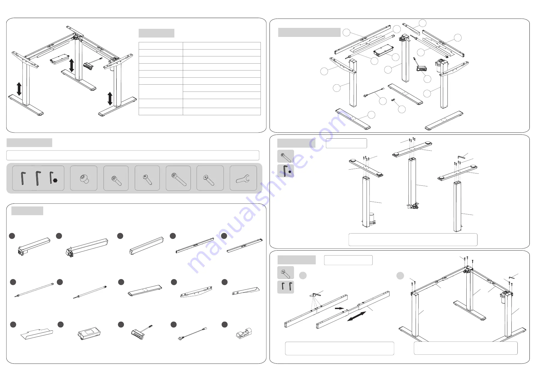
Accessory List
Attention: The drawings below are only for reference which might be slightly different from the physical objects, please refer to the actual product. If there are
any tools missing or installation problems, please contact customer service.
Part List
STEP1
STEP2
Installation Instruction
Assemble Table Legs
Connect the table legs (8) to the columns (1), (2), and (3), fix them with
screws (E), and tighten them with the 5 x 5 allen key (A).
Install Supporting Beam
Unscrew
Stretch
Loose screws on the long supporting beam (4) with the 4x4
allen key (A), then stretch supporting beam.
The operation of the short beam (5) is the same as above.
Install supporting beams (4)(5) on the column(1) (2)(3),
tighten the screw (F) with the 5x5 allen key (A).


