background image

06

06

13

13

13

13

28

28

25

V1.0 Pg.11/15

ITEM NO.

DESCRIPTION

QTY.BOX NO.1 QTY.BOX NO.2

06

Side L Plate 

2

-

13

Screw M5 XL10

4

-

25

Side L Plate 

-

1

28

Screw M5 XL10

-

2

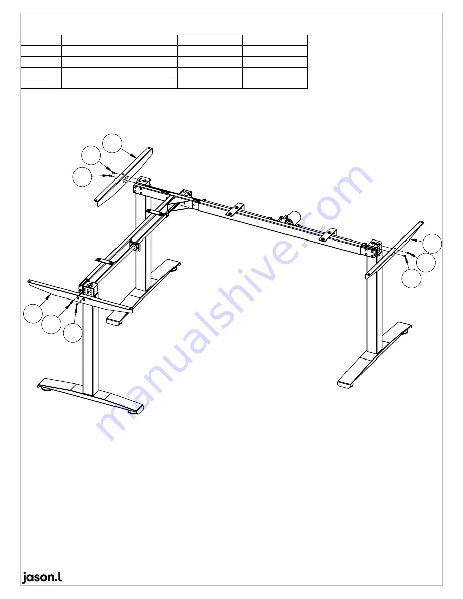
Assembly Instruction: Install Side L Plate

Summary of Contents for Sit-Stand Series

Page 1: ...ASSEMBLY INSTRUCTION MODEL ST SUPREME E25T 90 LEFT Electric L Shaped Desk Frame Table Top 150X150cm 180X150cm 180X180cm V1 0...

Page 2: ...y 1 Foot Qty 2 Crossbar Assy Qty 1 Screw M6XL10 Qty 3 Leveling Base Qty 4 Control Box TC11 Qty 1 Motor TGM1 2252 003 Qty 1 Rubber Pad Type A Qty 10 Crossbar Assy Qty 1 Side L Plate Qty 2 Screw M6 X L1...

Page 3: ...6 Right Column Qty 1 Foot Qty 1 Crossbar Assy Qty 1 Leveling Base Qty 2 Rubber Pad Type A Qty 7 Side L Plate Qty 1 Screw M6 X L16 Qty 4 NIL NIL 22 23 24 25 26 27 28 29 30 31 RHD Woodscrew M5X25 Qty 1...

Page 4: ...oot STEP 3 Install Crossbar Left Assy Step 1 Install Leveling Base ITEM NO DESCRIPTION QTY BOX NO 1 03 Foot 1 18 Leveling Base 2 ITEM NO DESCRIPTION QTY BOX NO 1 01 Left Column 1 15 Screw M6 XL16 4 IT...

Page 5: ...ot STEP 3 Install Crossbar Right Assy Step 1 Install Leveling Base ITEM NO DESCRIPTION QTY BOX NO 1 03 Foot 1 18 Leveling Base 2 ITEM NO DESCRIPTION QTY BOX NO 1 02 Right Column 1 15 Screw M6 XL16 4 I...

Page 6: ...oot STEP 3 Install Crossbar Right Assy Step 1 Install Leveling Base ITEM NO DESCRIPTION QTY BOX NO 2 23 Foot 1 31 Leveling Base 2 ITEM NO DESCRIPTION QTY BOX NO 2 22 Right Column 1 29 Screw M6 XL16 4...

Page 7: ...e Left Stand Assy Step 5 Adjust and align distance Refer table lower right side Step 6 Lock Set Screw M6 x8 Set Screw M6 X8 Detail A Detail B Detail C Pull out Axle Drive from Geax box Follow directio...

Page 8: ...14 14 14 19 V1 0 Pg 5 15 ITEM NO DESCRIPTION QTY BOX NO 1 14 Screw M6 XL10 3 19 Motor TGM1 2252 003 1 Assembly Instruction Install Motor Assembly...

Page 9: ...see attachment caution Refer Pg10 15 2 After insert Hex Shaft 11 Hex Shaft 09 and Axle Drive 08 align according as per Figure No 1 dimension 3 Align Axle Drive into gear box 4 Locking Set Screw M6 x4...

Page 10: ...t Hex Shaft make sure Left Stand Right Stand are at lowest position Please see attachment caution Refer Pg10 15 2 After insert Hex Shaft and Axle Drive align according as per Figure No 2 dimension 3 L...

Page 11: ...see attachment caution Refer Pg10 15 2 After insert Hex Shaft 10 Hex Shaft 09 and Axle Drive 08 align according as per Figure No 3 dimension 3 Align Axle Drive into gear box 4 Locking Set Screw M6 x4...

Page 12: ...d Right Stand are at lowest position Please see attachment caution Refer Pg10 15 2 After insert Hex Shaft 26 and Axle Drive align according as per Figure No 4 dimension 3 Locking Set Screw M6 V1 0 Pg...

Page 13: ...The marking O not appear means it is at lowest position refer to below diagram Marking fully seen Marking partially seen Marking not seen Means at lowest position Press Press V1 0 Pg 10 15 Caution Col...

Page 14: ...6 06 13 13 13 13 28 28 25 V1 0 Pg 11 15 ITEM NO DESCRIPTION QTY BOX NO 1 QTY BOX NO 2 06 Side L Plate 2 13 Screw M5 XL10 4 25 Side L Plate 1 28 Screw M5 XL10 2 Assembly Instruction Install Side L Plat...

Page 15: ...12 13 13 V1 0 Pg 12 15 ITEM NO DESCRIPTION QTY BOX NO 1 12 Cable Tray 1 13 Screw M5 XL10 2 Assembly Instruction Install Cable Tray...

Page 16: ...20 21 V1 0 Pg 13 15 ITEM NO DESCRIPTION QTY BOX NO 1 20 Control Box TC11 1 21 Handset TH14 1 Assembly Instruction Install Control Box Handset...

Page 17: ...7 17 17 17 17 17 17 17 17 30 30 30 30 30 30 30 17 V1 0 Pg 14 15 ITEM NO DESCRIPTION QTY BOX NO 1 QTY BOX NO 2 17 Rubber Pad Type A 10 30 Rubber Pad Type A 7 Assembly Instruction Plug Rubber Pad Type A...

Page 18: ...p and Down buttons simultaneously for more than 3 seconds until the desk moves down to lowest position After checking the signal motor constant reset was completed and ready to use The initialization...

Reviews: