background image

'DOWN BUTTON'

'UP BUTTON'

Pg.11/11

Reset operation as below :
1.One time reset 

    The first powered up, press and hold 'Down Button', the desk moving down

    to lowest position.

    After checking the signal motor constant, reset was completed and ready to

    use.
2.

Any dismantle of electrical component follow below procedure.

    Press both button up and down for 3-5 seconds to clear memory.

    Follow procedure no.1 again.

Assembly Instruction: Reset The Desk Before Use

Summary of Contents for ST SUPREME E23T

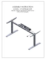
Page 1: ...ASSEMBLY INSTRUCTION MODEL ST SUPREME E23T Electric Height Adjustable Table Frame 4 to 6 Feet Length...

Page 2: ...01 Qty 1 Crossbar Motor Model CB 10 219 00 Qty 1 Cable Tray FA 00 220B 00 Qty 1 Right Column FA 20 106 ER 01 Qty 1 Foot FA 10 315 02 Qty 2 Crossbar Assy Left CB 10 217B 01 Qty 1 Screw M6XL10 Qty 3 Lev...

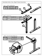
Page 3: ...nstall Crossbar Left Assy Step 1 Install Leveling Base ITEM NO DESCRIPTION QTY 03 Foot FA 10 315 02 1 17 Leveling Base 2 ITEM NO DESCRIPTION QTY 01 Left Column FA 20 106 L 01 1 15 Screw M6 XL16 4 ITEM...

Page 4: ...ll Crossbar Right Assy Step 1 Install Leveling Base ITEM NO DESCRIPTION QTY 03 Foot FA 10 315 02 1 17 Leveling Base 2 ITEM NO DESCRIPTION QTY 02 Right Column FA 20 106 ER 01 1 15 Screw M6 XL16 4 ITEM...

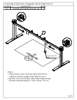
Page 5: ...right direction to adjust the frame length fixed table top size 2 Tighten set screw M6 X4 after fixed frame length Recommanded length 115cm 145cm 175cm ITEM NO DESCRIPTION QTY 07 Crossbar Motor Model...

Page 6: ...18 14 14 14 Pg 4 11 ITEM NO DESCRIPTION QTY 18 Motor TGM1 2252 002 1 14 Screw M6 XL10 3 Assembly Instruction Install Motor Assembly...

Page 7: ...Left Stand Right Stand are at lowest position Please see attachment caution Refer Pg7 11 2 Tighten set screw M6 X4 after fixed frame length Pg 5 11 ITEM NO DESCRIPTION QTY 08 Axle Drive L390mm ET 00 3...

Page 8: ...Left Stand Right Stand are at lowest position Please see attachment caution Refer Pg 7 11 2 Tighten set screw M6 X4 after fixed frame length Pg 6 11 ITEM NO DESCRIPTION QTY 8 Axle Drive L550mm ET 00...

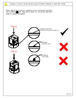
Page 9: ...on The marking O not appear means it is at lowest position refer to below diagram Marking fully seen Marking partially seen Marking not seen Means at lowest position Press Press Pg 7 11 Caution Column...

Page 10: ...06 06 13 13 13 13 Pg 8 11 ITEM NO DESCRIPTION QTY 06 Side L Plate FA 00 119 01 2 13 Screw M5 XL10 4 Assembly Instruction Install Side L Plate...

Page 11: ...M5 Notes Step 1 Place Control Box to Cable Tray Step 2 Plug Motor connector and Handset connector to control box Pg 9 11 ITEM NO DESCRIPTION QTY 12 Cable Tray FA 00 220B 00 1 13 Screw M5 XL10 2 ITEM N...

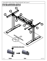
Page 12: ...16 16 16 16 16 16 16 16 16 16 Plug Rubber Pad Type T Pg 10 11 Before V1 0 After ITEM NO DESCRIPTION QTY 16 Rubber Pad Type T 10 Assembly Instruction Plug Rubber Pad Type T...

Page 13: ...n the desk moving down to lowest position After checking the signal motor constant reset was completed and ready to use 2 Any dismantle of electrical component follow below procedure Press both button...

Reviews: