background image


Parts 

1.


Flue gas extractor fan 

2.


90º flue swiveling joint 

3.


Filling port 

4.


Maintenance hatch 

5.


Cleanout 

6.


Air chamber hatch 

7.


Electric leads 

8.


R32 FH (female threaded) outlet to accu-
mulator 

9.


R32 FH return from accumulator 

10.


R15 FH drain connection 

11.


R25 FH expansion connection 

12.


R15 FH flue gas sensor / analyzer connec-
tion 

13.


Sensor panel 

14.


Flame monitor glass 

15.


Upper primary air adjusting damper 

16.


Lower primary air adjusting damper 

17.


Secondary air adjusting damper 

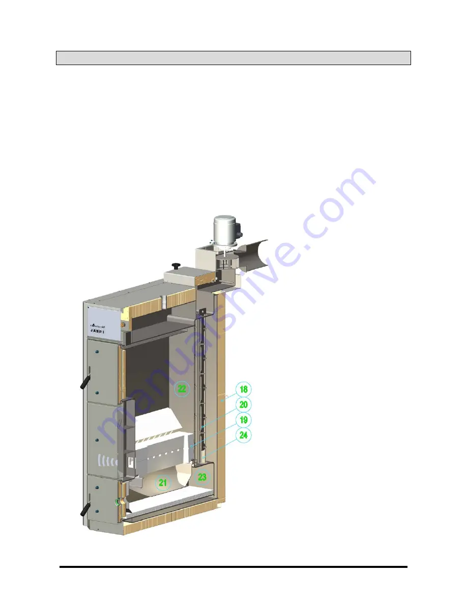
18.


Mineral wool insulation 75 mm 

19.


Ceramic fire bar 

20.


Turbulent components 

21.


Firing throat 

22.


Storage furnace 

23.


Furnace 

24.


Convection ducting


Summary of Contents for Econature40

Page 1: ...07 2011 SOLID FUEL BOILER INSTALLATION AND OPERATION MANUAL J SPI HEATING PROFESSIONAL www kaukora fi...

Page 2: ...t Connection Diagram 8 Boiler Operation and Maintenance 8 Fuel 8 Start up 9 Control Panel 9 Firewood burning 10 Combustion Air Control 11 Maintenance 12 Cleaning 13 Troubleshooting 13 The boiler water...

Page 3: ...ns at a temperature above 100 C when the temperature exceeds 280 C the resulting reaction causes heat re lease Secondary combustion the reaction between pyrolytic gases and oxygen begins at a temperat...

Page 4: ...ax temperature 110 C Min temperature 0 C Max pressure 3 0 bar Standard pressure 1 5 bar Proof test pressure 4 0 bar Power consumption 0 12 kW Voltage 230 V Frequency 50 Hz Body protection IP 2X Furnac...

Page 5: ...accumulator 10 R15 FH drain connection 11 R25 FH expansion connection 12 R15 FH flue gas sensor analyzer connec tion 13 Sensor panel 14 Flame monitor glass 15 Upper primary air adjusting damper 16 Low...

Page 6: ...extractor fan motor is changed Correct rota tion direction is marked on the flue swivelling joint with an arrow Boiler Room Leave free space of at least 1000 m in front of the filling and maintenance...

Page 7: ...r three maximum valves if necessary To confirm functionality at least two safety relief valves are recom mended to be used at all times each having the required blowoff capacity The blowoff line of th...

Page 8: ...ora tion and remove most of it through the stack as unburnt flue gases thus uselessly loosing part of energy and resulting in soot formation in the stack Firewood is considered dry when the moisture c...

Page 9: ...pera ture in the boiler 3 Pump thermostat 60 90 C Activates the charging pump when the boiler water achieves the setpoint The setpoint should be at least 85 C under normal operating conditions 4 Smoke...

Page 10: ...ard onto the bar so that the blocks touch the rear wall of the furnace Set the smoke exhauster thermostat to the setpoint which is about 90 C The set point is correct if the smoke exhauster stops when...

Page 11: ...and ratio for burning varies depending on the wood to be burnt Primary and secondary air is factory adjusted for birch firewood Upper primary air does not have to be ad justed under normal operating c...

Page 12: ...tains air oxygen The hot system pressure should be lower than 1 5 bar and the cold system pressure higher than 0 5 bar 1 5 bar safety relief The water volume varies as the tempera ture i e the higher...

Page 13: ...boiler water temperature does not rise to the desired level Ensure that the primary and secondary air ratio and access are correct Ensure that the firewood is dry If there is a cooling coil in the boi...

Page 14: ...that the thermostat indi cator lamp is on since the set value of the extractor thermostat is 90 C Check the set value of the flue gas ther mostat Check that the temperature limiter has not tripped For...

Page 15: ...170 C Reduced flue pressure Pump speed Pump speed Upper primary air 0 Lower primary air 0 Secondary air 0 Expansion tank pre pressure Signature Warranty The warranty is confirmed to be two years for t...

Page 16: ...dit agency Declared agency 0424 Inspecta EY inspection certificate for the development of RS 419 07 Testing has been conducted to EN 303 5 test agency SP Sveriges Tekniska Forskningsinstitut declared...

Reviews: