6.2. External Connections to the Boiler Terminal Strip
Power wire 240 V, 50/60 Hz. Fuses and power wire
determined for the unit according to the selected power rating.
See table below for maximum power options.
6.3. Electric Boiler Power Table
Step
Power (kW)
Current (A)
1
1.6 7
2
3.2 13
3
4.8 20
4
7.6 32
5
10.4 43
6*
13.2 55
*= factory setting
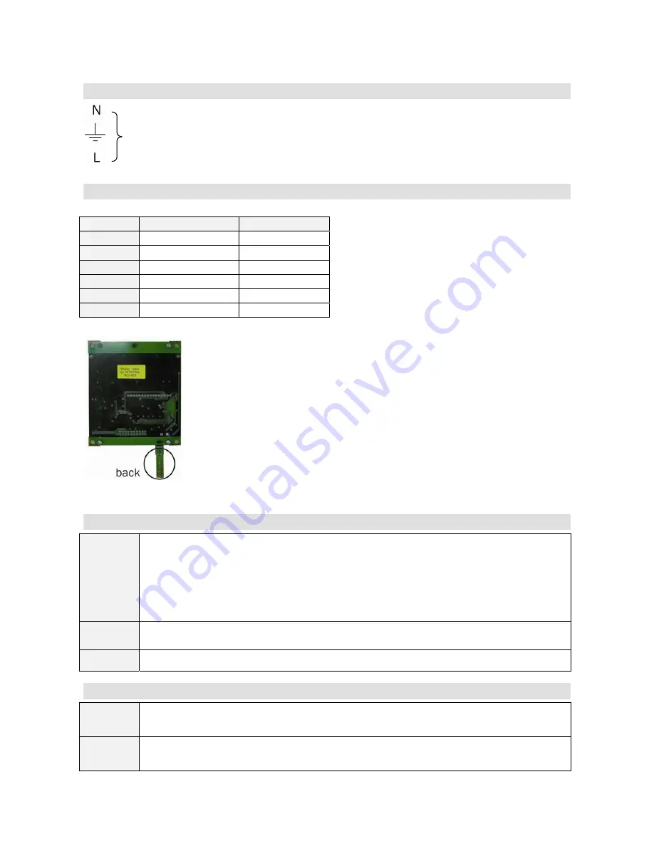
Picture 1. maximum power control
6.4. PCB Low Current Terminals – Standard Supply
6 – 7
- Installed to look to the north-west on the shadowed external wall of the house at a
distance from the vent valves.
- Ensure that melt water and icing will not cause damage to the sensor.
- If the outdoor sensor is installed near the wall inlet, make sure that the inlet is
insulated properly.
10 – 11
Connection of current transformer, wiring separately from power cables e.g. 2 x 1,5 N.
Connected at the central board of the house for measuring total current on site
.
2 - 3
Connection to external heating system e.g. heat pump. 240 VAC max. 5A.
6.5. PCB Low Current Terminals – Optional Supply
8 – 9
- Optional external potential free control e.g. for clockwork or temperature drop switch
in case you leave the house. Normally open.
4 – 5
- Remote controller = optional supply. If outdoor sensor is connected remote controller
can be used for fine adjusting of outdoor temperature curve.
Summary of Contents for PW
Page 4: ...3 1 Function Diagram...
Page 10: ...7 Electrical Diagram...
Page 13: ...9 1 Front Panel...


