2-8
LGG100 Operator’s Manual
www.javad.com
S E T U P A N D M E A S U R I N G
DGPS Measuring with the LGG100
2
•
Output
drop-down list – select type and format of differential
corrections (Figure 2-7).
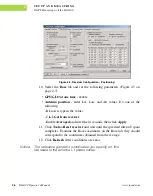
Figure 2-7. Port output setup
•
Period
(sec) – enter interval at which receiver will generate differential
corrections.
•
Baud rate
drop-down list – select a baud rate (i.e., the rate at which
differential messages will be transmitted from receiver to modem).
14. Click
Apply
. The receiver begins sending data to the selected port.
Notice:
Connect the radio antenna before switching the modem
to the transmitting mode.
15. When finished with the previous steps, press the power button on the
external modem.
16. Select the radio transmission power using the Low/High toggle on the
rear panel of the modem.
17. Use the
Channel
button to set the frequency channel. Check that the
modem transmits the corrections (the TX LED will blink red each time
data transmits).
For more details on the settings available for configuring the Base
station, refer to the
PCView Software Manual
.
Summary of Contents for LGG100
Page 2: ......
Page 6: ...iv LGG100 Operator s Manual www javad com Notes ...
Page 8: ...vi LGG100 Operator s Manual www javad com Notes ...
Page 24: ...1 10 LGG100 Operator s Manual www javad com Notes ...
Page 50: ...4 8 LGG100 Operator s Manual www javad com Notes ...
Page 58: ...B 6 LGG100 Operator s Manual www javad com APPENDIX Specifications B ...


