background image

- 57 -

ISIS

  -  331260D 

revision02

DE

FR

EN

2 -  Presentation of ISIS series

For any questions or recommendations related to installation 
of the 

ISIS series

, contact our «

Customer technical support 

department

» :

Monday to Friday

Phone : +33.(0)4.76.41.44.00
Fax : +33.(0)4.76.41.44.44
Email : support.technique.client@jay-electronique.fr

Thank you for choosing our 

ISIS

 data transmission system 

which will provide you the highest level of reliability.

The 

ISIS Series

 generates logical signal transfers (mono or 

bidirectional) for a broad range of applications, including :

- Industrial equipment
- Infrastructure
- Industrial lifting system
- Agricultural equipment

The 

ISIS Series

 fully satis

fi

 es the safety requirements of the current 

applicable and draft standards and is compliant with European 
directive  :

RTTE

 :  Microwave equipment and telecommunication terminals (low 

voltage, electromagnetic compatibility, radio spectrum).

Summary of Contents for ISIS Series

Page 1: ...sans fil Notice d installation et d utilisation page 3 Annexes page 42 Wireless data transmission system Installation and user technical manual page 53 Appendix page 92 Kabelloses Daten bertragungssy...

Page 2: ...2 ISIS 331260D revision02...

Page 3: ...3 ISIS 331260D revision02 DE FR EN Notice technique d installation et d utilisation Syst me de transmission d informations sans fil Report d tats logiques ISIS...

Page 4: ...metteur transmetteur p 15 4 4 Puissance d mission radio de l metteur transmetteur p 16 4 5 Relais RM Qualit radio p 17 4 6 Synchronisation des transmetteurs IST p 17 5 Mise en route rapide p 18 5 1 Pr...

Page 5: ...38 8 2 R cepteurs ISR et module r cepteur du transmetteur IST p 39 9 Entretien et maintenance p 40 10 Garantie p 41 11 Annexes p 42 11 1 Caract ristiques radio lectriques p 42 11 2 Caract ristiqueste...

Page 6: ...d utilisation il est recommand de respecter les instructions fournies dans ce manuel L alimentation doit tre conforme la norme EN60950 EN50081 1 CEM doit comporter le marquage CE et doit respecter le...

Page 7: ...u rir le syst me de transmission d informations sans fil S rie ISIS qui vous propose un haut niveau de fiabilit La S rie ISIS est destin e au report d tats logiques mono ou bidirectionnel pour des dom...

Page 8: ...ercle il est fortement conseill de modifier le code d identit afin d assurer l unicit de votre installation voir chapitre Modification de la configuration usine 3 2 Identification des produits la livr...

Page 9: ...er de codage JP3 F1 Fusible voir chapitre 11 4 A Bornier alimentation F2 Fusible voir chapitre 11 4 B Bornier sorties relais 3 2 2 R cepteur ISRS 4 sorties relais 3 2 3 R cepteur ISRA 8 sorties relais...

Page 10: ...e programmation JP2 Cavalier de codage JP2 V3 Voyant vert r ception radio JP3 Cavalier de codage JP3 F1 Fusible voir chapitre 11 4 A Bornier alimentation F2 Fusible voir chapitre 11 4 B Bornier sortie...

Page 11: ...r metteur et relais de sortie sur r cepteur affectation fig e ne peut pas tre modifi e Entr es metteur Relais de sortie command s sur r cepteur ISE IST ISRS ISRA IST 1 R1 R1 2 R2 R2 3 R3 R3 4 R4 R4 5...

Page 12: ...ule r cepteur du 2eme transmetteur IST associ et inversement La transmission des tats logiques s effectue sur un canal radio avec un identifiant cod code d identit IMPORTANT Il est fortement conseill...

Page 13: ...13 ISIS 331260D revision02 DE FR EN Entr e n X Entr e n X Entr e n Y Sortie n X Sortie n X Sortie n Y Emetteur ISE Transmetteur IST n 1 Transmetteur IST n 2 R cepteur ISRS ISRA X...

Page 14: ...ut 3 Input 2 Input 1 Power lectronique INSTALLATION INCORRECTE INSTALLATION CORRECTE Les 2 ensembles A et B ont le m me code d identit Le code 11111111 est le code par d faut la livraison Emetteur A R...

Page 15: ...es est active Ce mode est pr conis pour des applications o plusieurs metteurs seront associ s un seul r cepteur Dans ce cas il faudra s assurer que les metteurs ISIS n mettent pas de la radio simulta...

Page 16: ...metteur et r cepteur ISIS est faible ou si le temps de r ponse d une sortie doit tre rapide inf rieure 60ms max il sera pr f rable de choisir une puissance d mission 1 mW Rappel un transmetteur IST co...

Page 17: ...nte ou en mode d mission intermittente d s qu une entr e est active 4 6 Synchronisation des transmetteurs IST Lorsque l installation comporte des transmetteurs IST ceux ci doivent tre synchronis s La...

Page 18: ...orm ment au sch ma ci dessous en respectant le branchement de l alimentation suivant le mod le utilis R1 R2 R2 R3 R4 4 5 6 7 8 9 10 11 12 13 1 2 3 4 5 6 7 8 9 10 11 12 13 16 17 18 19 20 21 14 15 RM R1...

Page 19: ...menter l metteur et le r cepteur ou les transmetteurs Emetteur ISE ou modules metteurs des transmetteurs IST Un auto test est effectu les voyants i1 i8 clignotent de fa on s quentielle Les voyants Va...

Page 20: ...ule metteur du transmetteur IST 1 2 ON 3 4 5 6 7 8 ID 0 1 Le code d identit se programme au moyen du DIP switch 8 curseurs ID curseur sur la position ON 1 Exemple Les autres configurations canal radio...

Page 21: ...0 1 0 0 1 05 17 433 500 1 1 0 0 1 06 21 433 600 0 0 1 0 1 07 25 433 700 1 0 1 0 1 08 29 433 800 0 1 1 0 1 09 33 433 900 1 1 1 0 1 10 37 434 000 0 0 0 1 1 11 41 434 100 1 0 0 1 1 12 45 434 200 0 1 0 1...

Page 22: ...uit Suivre la proc dure en page suivante Pr caution prendre Si vous ne modifiez pas le code d identit vous pouvez passer directement l tape n 2 dans ce cas il n est pas n cessaire de placer les cavali...

Page 23: ...angement de configuration est transmis au r cepteur Si l association metteur r cepteur n a pas fonctionn par ex le r cepteur tait hors tension au moment de l association Appuyer et maintenir le bouton...

Page 24: ...pteur IST_2 puis Module metteur IST_2 Module r cepteur IST_1 IMPORTANT la synchronisation doit tre active sur l un des deux transmetteurs voir chapitre Synchronisation des transmetteurs IST Chaque cou...

Page 25: ...pteur transmetteur IST Etape Actions r aliser et tat des voyants du r cepteur ou du module r cepteur du transmetteur 1 2 3 Mettre le r cepteur ou le transmetteur hors tension 4 Mettre le r cepteur ou...

Page 26: ...ion Placer les cavaliers JP2 et JP3 Mettre ensuite le r cepteur ou le transmetteur sous tension La visualisation du code d identit est r alis e par les voyants V2 et V3 Le code identit est cod sur 8 b...

Page 27: ...as les parois m talliques les antennes ne doivent pas tre plac es dans une enceinte formant un blindage tel que armoire m tallique mur en b ton arm charpente ou paroi m tallique etc Dans de tels cas l...

Page 28: ...onges d antenne disponibles r f VUB170 rallonge de 0 5m connectique BNC sans support r f VUB105 rallonge de 2m connectique BNC avec support r f VUB125 rallonge de 5m connectique BNC avec support r f V...

Page 29: ...er entre 2 ensembles ISIS de m me puissance 1 ou 10mw E4 E1 E2 E3 P1 P2 d1 d2 2 Condition 1 Pr voir au minimum 2 canaux radio d cart entre les 2 ensembles ISIS Exemple canal n 5 pour l ensemble E1 E2...

Page 30: ...ISIS Exemple si la port e P1 entre E1 et E2 est de 90m la distance minimum d2 entre E2 et E3 devra tre de 3m Note Ces distances sont th oriques et d pendent des conditions d environnement Distance mi...

Page 31: ...c une puissance de 10mW Exemple d application Condition 1 Pr voir de r gler le canal radio de l ensemble ISIS une fr quence sup rieure celle utilis e par la radiocommande JAY Electronique Condition 2...

Page 32: ...rt entre le canal radio de l ensemble ISIS et une autre radiocommande JAY Electronique est de 200KHz Note 1 Ces distances sont th oriques et d pendent des conditions d environnement Note 2 Dans le cas...

Page 33: ...re Au cas ou un seul chemin de c ble serait disponible on cartera au maximum les c bles de classes diff rentes 7 3 2 Raccordement sur les borniers ressort En cas d utilisation de fils multibrins soupl...

Page 34: ...entation suivant mod le du r cepteur ISR ou du module r cepteur du transmetteur IST V2 JP1 RM R1 R2 R3 R4 JP2 JP3 V1 V3 4 5 6 7 8 9 10 11 12 13 1 2 3 1 2 3 1 2 3 1 2 3 1 2 3 JP1 4 5 6 7 8 9 10 11 12 1...

Page 35: ...3 4 5 6 7 8 C 1 2 3 4 5 6 7 8 B 0v 3 30Vdc 0v 3 30Vdc 0v 3 30Vdc Contacts secs sur les entr es Emetteur ISE Module metteur du transmetteur IST Pour alimenter les entr es du module metteur du transmet...

Page 36: ...relais du r cepteur V2 JP1 RM R1 R1 R2 R3 R4 R2 R3 R4 JP2 JP3 V1 V3 4 5 6 7 8 9 10 11 12 13 1 2 3 JP1 4 5 6 7 8 9 10 11 12 13 16 17 18 19 20 21 14 15 RM R1 R2 R3 R4 R5 R6 R7 R8 V2 V1 V3 JP2 JP3 1 2 3...

Page 37: ...ble Il convient galement d utiliser une r sistance de tirage sur les entr es automates Exemples de syst me de protection utiliser 7 5 Courant minimum et maximum des sorties relais Veillez ne pas d pas...

Page 38: ...llume pas Les c bles sur l entr e ne sont pas correctement ins r s dans le bornier ressort Rebrancher correctement les c bles La tension sur l entr e est inf rieure 3V V rifier le circuit de commande...

Page 39: ...transmetteur n 1 est sur le m me canal radio que l metteur ou module metteur du transmetteur n 2 Reprendre la proc dure de programmation du canal radio Le voyant rouge V2 s allume apr s la mise sous...

Page 40: ...s solvants de polym res ou des colles pouvant d grader le bon fonctionnement des produits V rifier r guli rement les points suivants Les branchements des alimentations des entr es et des sorties Les c...

Page 41: ...de stockage d exploitation ou d environnement influences atmosph riques chimiques lectriques m caniques ou autres non appropri es ou non pr vues lors de la commande La garantie ne peut s exercer si de...

Page 42: ...disponibles 8 Bandes de fr quence ISM 433 434Mhz Modulation FM Canaux radio 18 canaux programmables Espacement de 100KHz partir de 433 1 434 7MHz le 18eme sur 434 740MHz Puissance apparente rayonn e I...

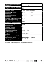
Page 43: ...ontinue 3 V Niveau de tension maximum sur une entr e sans dommage 30 V Tenue au transitoire rapide sur l alimentation en couplage direct 2KV Tenue aux d charges lectrostatiques 4 kV Tenue aux champs l...

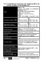
Page 44: ...adio Type de sortie Relais avec 1 contact fermeture Antenne Fixe standard ou externe type BNC r f VUB084 gr ce au kit r f OWR01 Sensibilit tuner 2 V Protection fusible Fusibles sur support calibres su...

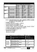
Page 45: ...ut e par le relais Nombre de commutation pour les relais de sortie CA2DN LC1D09 LC1D18 LC2D09 Commutation sous 230VAC 70VA cosphi 0 75 2 x 10 6 Commutation sous 110VAC 70VA cosphi 0 75 1 x 10 6 Commut...

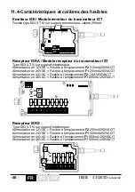
Page 46: ...VAC Fusible l emplacement F2 1 6A 250VAC T Alimentation en 48 VAC Fusible l emplacement F1 800mA 250VAC T 1 2 ON 3 4 5 6 7 8 1 2 ON 3 4 5 6 7 8 DC A CONFIG ID F1 C 1 2 3 4 5 6 7 8 B 4 5 6 7 8 9 10 11...

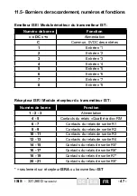
Page 47: ...Entr e n 8 Num ro de borne Fonction 1 2 3 Alimentation 4 5 Contacts du relais Qualit radio RM 6 7 Contacts du relais de sortie R1 8 9 Contacts du relais de sortie R2 10 11 Contacts du relais de sorti...

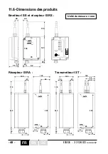
Page 48: ...ur ISRA Transmetteur IST 19 lectronique 25 50 123 170 92 79 108 2x 4 26 20 25 lectronique Input 8 Input 7 Input 6 Input 5 Input 4 Input 3 Input 2 Input 1 Power Set 229 90 66 120 47 35 48 27 100 4x 4 l...

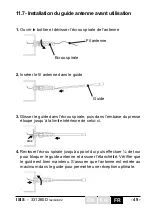
Page 49: ...e fil antenne dans le guide 3 Glisser le guide dans l crou spirale puis dans l embase du presse toupe jusqu la limite int rieure de celui ci 4 Revisser l crou spirale jusqu au point dur puis effectuer...

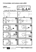
Page 50: ...tallation du kit antenne externe BNC Fr lectronique lectronique OWR01 OWR01 A B C A B C A B C 1 1 2 2 3 3 4 4 Kit antenne externe Emetteur ISE R cepteur ISRS Module metteur du transmetteur IST R cepte...

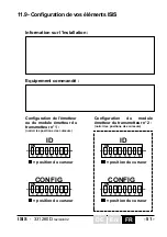
Page 51: ...D 1 2 ON 3 4 5 6 7 8 CONFIG 1 2 ON 3 4 5 6 7 8 ID 1 2 ON 3 4 5 6 7 8 CONFIG position du curseur position du curseur position du curseur position du curseur Configuration de l metteur ou du module mett...

Page 52: ...52 ISIS 331260D revision02 FR DE EN...

Page 53: ...53 ISIS 331260D revision02 DE FR EN Installation and user technical manual Wireless data transmission system Logic state indication ISIS...

Page 54: ...modes p 65 4 4 Transmitter radio transmit power p 66 4 5 Radio quality RM relay p 67 4 6 Synchronizing transceivers IST p 67 5 Quick startup p 68 5 1 Preliminary remarks p 68 5 2 Connecting the receiv...

Page 55: ...roblem p 88 8 1 Transmitter ISE and transceiver transmitter module IST p 88 8 2 Receiver ISR and transceiver receiver module IST p 89 9 Inspection and servicing p 90 10 Warranty p 91 11 Appendices p 9...

Page 56: ...use be sure to apply the instructions given in this manual The power supply must be compliant with the requirements of standard EN60950 EN50081 1 EMC must carry the CE marking and must have the elect...

Page 57: ...IS data transmission system which will provide you the highest level of reliability The ISIS Series generates logical signal transfers mono or bidirectional for a broad range of applications including...

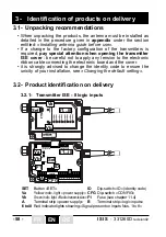
Page 58: ...s strongly advised to change the identity code to ensure the unicity of your installation see Changing the default setting 3 2 Product identification on delivery lectronique Set Input 8 Input 7 Input...

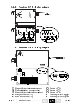
Page 59: ...n JP3 Jumper JP3 F1 Fuse see chapter 11 4 A Term strip Power supply F2 Fuse see chapter 11 4 B Term strip Relay outputs 3 2 2 Receiver ISRS 4 relay outputs 3 2 3 Receiver ISRA 8 relay outputs RM R1 R2...

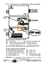
Page 60: ...reception JP3 Jumper JP3 F1 Fuse see chapter 11 4 A Term strip Power supply F2 Fuse see chapter 11 4 B Term strip Relay outputs 8 logic inputs transmitter Module SET Button SET ID Dip switch ID identi...

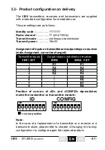
Page 61: ...nsmitter and output relays on receiver static Assignment can not be changed Transmitter inputs Output relays controlled on receiver ISE IST ISRS ISRA IST 1 R1 R1 2 R2 R2 3 R3 R3 4 R4 R4 5 R5 6 R6 7 R7...

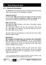
Page 62: ...ceiver module of the 2nd transceiver IST and vice versa The logic states are transmitted on a radio channel with a coded identifier identity code IMPORTANT We strongly recommend that you configure you...

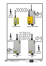
Page 63: ...63 ISIS 331260D revision02 DE FR EN Input nb X Input nb X Input nb Y Output nb X Output nb X Output nb Y Transmitter ISE Transceiver IST nb 1 Transceiver IST nb 2 Receiver ISRS ISRA Y...

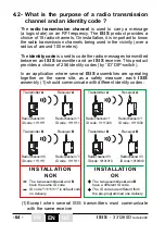
Page 64: ...e receiver lectronique Set Input 8 Input 7 Input 6 Input 5 Input 4 Input 3 Input 2 Input 1 Power lectronique INSTALLATION NOK INSTALLATION OK The two assemblies A and B have the same ID code ID code 1...

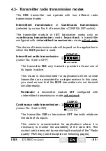
Page 65: ...its inputs is active This mode is recommended for applications where several transmitters are associated to a single receiver In this case you must ensure that the ISIS transmitters do not transmit s...

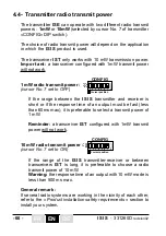
Page 66: ...receiver is short or if the response time of an output must be fast less than 60ms max it is preferable to select a transmit power of 1 mW Reminder a transceiver IST configured with 1mW transmit powe...

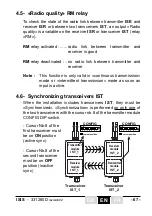
Page 67: ...or intermittent transmission mode as soon an input is active 4 6 Synchronizing transceivers IST When the installation includes transceivers IST they must be Synchronized Synchronization is performed...

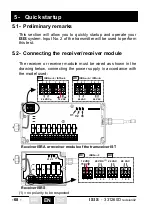
Page 68: ...n the drawing below connecting the power supply in accordance with the model used R1 R2 R2 R3 R4 4 5 6 7 8 9 10 11 12 13 1 2 3 4 5 6 7 8 9 10 11 12 13 16 17 18 19 20 21 14 15 RM R1 R3 R4 R5 R6 R7 R8 V...

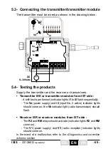
Page 69: ...he transmitter and the receiver or transceivers Transmitter ISE or transmitter modules from IST side A self test is performed indicator lights i1 to i8 flash sequentially The Va power supply and i2 in...

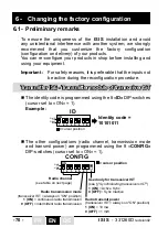
Page 70: ...sceiver IST Transmitter ISE Transmitter module of transceiver IST 1 2 ON 3 4 5 6 7 8 ID 0 1 The identity code is programmed using the 8 ID DIP switches cursor set to ON 1 Example The other configurati...

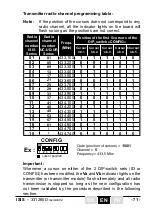
Page 71: ...0 1 1 0 0 1 06 21 433 600 0 0 1 0 1 07 25 433 700 1 0 1 0 1 08 29 433 800 0 1 1 0 1 09 33 433 900 1 1 1 0 1 10 37 434 000 0 0 0 1 1 11 41 434 100 1 0 0 1 1 12 45 434 200 0 1 0 1 1 13 49 434 300 1 1 0...

Page 72: ...there is no need to short circuit jumpers JP1 and JP3 on the receiver IMPORTANT Beware that this procedure can unintentionally associate another ISIS receiver using the same identity code Before you...

Page 73: ...nge of configuration is transmitted to the receiver If the transmitter receiver association has not operated for example receiver shutdown at moment of association Press and hold the SET button for 3...

Page 74: ...le IST_2 puis Transmitter module IST_2 Receiver module IST_1 IMPORTANT synchronization must be active on one of the two transceivers see Synchronizing Transceivers IST Each Module Transmitter Receiver...

Page 75: ...en switch on the receiver or the transceiver The radio channel currently used by the receiver is displayed by indicator lights V2 and V3 V2 indicates the tens if ON 10 if OFF 0 V3 indicates the units...

Page 76: ...r 1 position of the 8 bits of the identity code V1 V2 V3 V2 V2 V2 V3 V3 V3 Example Identity code 00111010 JP1 JP2 JP3 4 Switch off the receiver transceiver Remove jumpers JP2 and JP3 JP1 JP2 JP3 6 4 D...

Page 77: ...dio waves do not travel through metal walls The antennas must therefore not be placed in an enclosure forming a shield such as a metal cabinet a reinforced concrete wall a steel structure or metal wal...

Page 78: ...able ref VUB170 0 5m extension BNC connector without bracket ref VUB105 2m extension BNC connector with bracket ref VUB125 5m extension BNC connector with bracket ref VUB131 10m extension BNC connecto...

Page 79: ...lies with same transmit power 1 or 10mw Condition 1 Ensure a spacing of at least 2 radio channels between the two ISIS assemblies Example channel No 5 for assembly E1 E2 and radio channel No 7 for ass...

Page 80: ...Example if range P1 between E1 and E2 is 90m the minimum d2 between E2 and E3 must be 3 m Note These distances are theoretical and depend on the environment conditions Minimum distance to be respecte...

Page 81: ...mW transmit power Application example Condition 1 Be sure to set the radio channel of the ISIS assembly for a frequency greater than that used by the JAY Electronique radio remote control Condition 2...

Page 82: ...the ISIS assembly and another JAY Electronique remote control is 200KHz Note 1 These conditions are theoretical and depend on the environment conditions Note 2 If the ISIS assembly is operating in th...

Page 83: ...e path specific to the cable If only one cable path is available the cables of different classes should be separated as much as possible 7 3 2 Terminal strips If flexible stranded wire is used crimped...

Page 84: ...er power supply depending on version V2 JP1 RM R1 R2 R3 R4 JP2 JP3 V1 V3 4 5 6 7 8 9 10 11 12 13 1 2 3 1 2 3 1 2 3 1 2 3 1 2 3 JP1 4 5 6 7 8 9 10 11 12 13 16 17 18 19 20 21 14 15 RM R1 R2 R3 R4 R5 R6...

Page 85: ...4 i5 i6 i7 i8 2 3 4 5 6 7 8 C 1 2 3 4 5 6 7 8 B 0v 3 to 30Vdc 0v 3 to 30Vdc 0v 3 to 30Vdc Dry contacts on inputs Transmitter ISE Transceiver transmitter module IST To supply the transmitter module inp...

Page 86: ...outputs V2 JP1 RM R1 R1 R2 R3 R4 R2 R3 R4 JP2 JP3 V1 V3 4 5 6 7 8 9 10 11 12 13 1 2 3 JP1 4 5 6 7 8 9 10 11 12 13 16 17 18 19 20 21 14 15 RM R1 R2 R3 R4 R5 R6 R7 R8 V2 V1 V3 JP2 JP3 1 2 3 6 7 8 9 10 1...

Page 87: ...g the shortest possible connections A draw resistor should also be used on the controller inputs Examples of protection system to be used 7 5 Minimum and maximum current of relay outputs Be sure not t...

Page 88: ...dicator light does not come on Cables on inputs not correctly inserted in spring terminal strip Reconnect cables correctly Voltage on input is less than 3V Check control circuit When transmitter is sw...

Page 89: ...ver or receiver module of transceiver nb 1 is on same radio channel as transmitter or transmitter module of transceiver nb 2 Repeat radio channel programming procedure Red indicator light V2 comes on...

Page 90: ...ng polymer solvents or adhesives which could downgrade correct operation of the products Regularly check the following points Connection of power supplies inputs and outputs Control relay contacts Con...

Page 91: ...nvironment conditions atmospheric chemical electrical or other conditions Conditions not specified on order of the equipment The warranty shall not apply subsequent to any modifications or additions t...

Page 92: ...mber of available input 8 Transmit frequency bands ISM 433 434Mhz Modulation FM Radio channels 18 user programmable Steps 100KHz from 433 1 to 434 7MHz the 18th 434 740MHz Effective radiated power ISE...

Page 93: ...voltage level on an input with no damage 30 V Withstand capacity relative to fast power supply transients with direct connection 2KV Withstand capacity relative to electrostatic discharges 4 kV Withst...

Page 94: ...24VDC 20 to 28VDC AC 24VAC 10 15 48VAC 10 15 Number of output ISRS 4 1 Radio quality ISRA IST 8 1 Radio quality Type of output Relays with 1 NO contact Antenna Fixed standard or BNC external type ref...

Page 95: ...unit switched by relay Number of switching cycles for output relays CA2DN LC1D09 LC1D18 LC2D09 Switching under 230VAC 70VA cosphi 0 75 2 x 10 6 Switching under 110VAC 70VA cosphi 0 75 1 x 10 6 Switch...

Page 96: ...Fuse at location F2 1 6A 250VAC T Supplied with 48 VAC Fuse at location F1 800mA 250VAC T 4 5 6 7 8 9 10 11 12 13 16 17 18 19 20 21 14 15 RM R1 R2 R3 R4 R5 R6 R7 R8 1 2 3 F1 F2 Receiver ISRS Type 663...

Page 97: ...t nb 6 7 Input nb 7 8 Input nb 8 Terminal number Function 1 2 3 Power supply 4 5 Radio quality RM relay contacts 6 7 Contacts of R1 output relay 8 9 Contacts of R2 output relay 10 11 Contacts of R3 ou...

Page 98: ...ceiver ISRA 19 lectronique 25 50 123 170 92 79 108 2x 4 26 20 25 lectronique Input 8 Input 7 Input 6 Input 5 Input 4 Input 3 Input 2 Input 1 Power Set Unit mm Transceiver IST 229 90 66 50 120 47 35 48...

Page 99: ...2 Insert the antenna wire in the guide 3 Slide the guide into the spiral nut then fully into the cable gland base upto the limit in the base 4 Tighten the spiral nut to the sticking point then add a q...

Page 100: ...nstallation of external BNC antenna kit Fr lectronique lectronique OWR01 OWR01 A B C A B C A B C 1 1 2 2 3 3 4 4 External antenna kit Transmitter ISE Receiver ISRS Transceiver transmitter module IST R...

Page 101: ...1 2 ON 3 4 5 6 7 8 ID 1 2 ON 3 4 5 6 7 8 CONFIG 1 2 ON 3 4 5 6 7 8 ID 1 2 ON 3 4 5 6 7 8 CONFIG cursor position cursor position cursor position cursor position Transmitter configuration or Transceive...

Page 102: ...102 ISIS 331260D revision02 FR DE EN...

Page 103: ...103 ISIS 331260D revision02 DE FR EN Technische Notiz und Benutzerhandbuch Kabelloses Daten bertragungssystem Logische Statussignale ISIS...

Page 104: ...in Funkkanal und ein Identit tscode s 114 4 3 Sender Transceiver Funkmodus s 115 4 4 Funkst rke des Senders s 116 4 5 RM Relais Funkqualit t s 117 4 6 Synchronisierung der Transceiver IST s 117 5 Rasc...

Page 105: ...m Problemfall s 138 8 1 Sender ISE und Sendermodul Transceiver IST s 138 8 2 Empf nger ISR und Empf ngermodul Transceiver IST s 139 9 Kontrolle und Wartung s 140 10 Garantie s 141 11 Anhang s 142 11 1...

Page 106: ...und Nutzung m ssen die in diesem Handbuch gegebenen Sicherheitsanweisungen beachtet werden Die Stromversorgung muss der Norm EN60950 EN50081 1 EMV entsprechen die Kennzeichnung CE tragen und die in d...

Page 107: ...nssystem der Serie ISIS erstanden das Ihnen erh hte Zuverl ssigkeit bietet Die Serie ISIS ist f r die bertragung logische Statussignale Mono oder bidirektional f r folgende unterschiedlicheAnwendungsb...

Page 108: ...fohlen den Identit tscode zu ndern um die Einheitlichkeit Ihrer Anlage zu gew hrleisten Mehr dazu im Kapitel nderung der Werkskonfiguration 3 2 Produktidentifizierung lectronique Set Input 8 Input 7 I...

Page 109: ...Sicherung Siehe Kapitel 11 4 A Klemm Stromversorgung F2 Sicherung Siehe Kapitel 11 4 B Klemm Relaisausg nge 3 2 2 Empf nger ISRS 4 Relaisausg nge 3 2 3 Empf nger ISRA 8 Relaisausg nge RM R1 R2 R3 R4...

Page 110: ...mmierung JP2 Jumper JP2 V3 Gr ne LED Empfang Funksignal JP3 Jumper JP3 F1 Sicherung Siehe Kapitel 11 4 A Klemm Stromversorgung F2 Sicherung Siehe Kapitel 11 4 B Klemm Relaisausg nge Modul Sender 8 log...

Page 111: ...Sendest rke 10mW Zuordung der Sendereing nge und Empf ngerausgangsrelais unver nderlich Sendereing nge Gesteuerte Empf ngerausgangsrelais ISE IST ISRS ISRA IST 1 R1 R1 2 R2 R2 3 R3 R3 4 R4 R4 5 R5 6 R...

Page 112: ...vers IST schickt den Logikzustand seiner Eing nge an das Empf ngermodul des 2 und zugeordneten Transceivers IST Die bertragung der logischen Status erfolgt ber einen Funkkanal mit einem Identit tscode...

Page 113: ...113 ISIS 331260D revision02 DE FR EN Eingang Nr X Ausgang Nr X Eingang Nr X Eingang Nr Y Ausgang Nr X Ausgang Nr Y Sender ISE Transceiver IST Nr 1 Transceiver IST Nr 2 Empf nger ISRS ISRA...

Page 114: ...nger kommunizieren m ssen lectronique Set Input 8 Input 7 Input 6 Input 5 Input 4 Input 3 Input 2 Input 1 Power lectronique INSTALLATION NICHT KORREKT INSTALLATION KORREKT Die beiden Systeme A und B...

Page 115: ...e aktiv ist Dieser Modus wird f r Anwendungen empfohlen bei denen mehrere Sender demselben Empf nger zugeordnet werden In diesem Fall muss sichergestellt werden dass die ISIS Sender nicht gleichzeitig...

Page 116: ...ischen ISIS Sender und Empf nger schwach ist oder wenn die Reaktionszeit eines Ausganges rasch sein muss unter 60 ms sollte besser eine Funkst rke 1 mW gew hlt werden Hinweis Ein auf eine Funksendelei...

Page 117: ...n ist nur im durchgehenden Funkmodus verf gbar oder im diskontinuierlichen Funkmodus sobald ein Ausgang aktiv ist Wenn die Installation Transceiver IST enth lt m ssen diese synchronisiert werden Die S...

Page 118: ...uss verkabelt sein und nachstehender Zeichnung entsprechen Dabei muss der Anschluss der Stromversorgung dem benutzten Modell entsprechen R1 R2 R2 R3 R4 4 5 6 7 8 9 10 11 12 13 1 2 3 4 5 6 7 8 9 10 11...

Page 119: ...chen 5 4 Test der Produkte Sender und Empf nger oder beide Transceiver einschalten Seite Sender ISE Sendermodul IST Es wird ein Autotest durchgef hrt die LED i1 und i8 blinken auf sequentielle Weise D...

Page 120: ...des Transceivers IST Sender ISE Sendermodul des Transceivers IST 1 2 ON 3 4 5 6 7 8 ID 0 1 Der Identit tscode wird anhand des DIP Schalters mit 8 Cursors ID im Inneren programmiert Cursor auf Position...

Page 121: ...06 21 433 600 0 0 1 0 1 07 25 433 700 1 0 1 0 1 08 29 433 800 0 1 1 0 1 09 33 433 900 1 1 1 0 1 10 37 434 000 0 0 0 1 1 11 41 434 100 1 0 0 1 1 12 45 434 200 0 1 0 1 1 13 49 434 300 1 1 0 1 1 14 53 4...

Page 122: ...all m ssen die Reiter JP1 und JP3 auf dem Empf nger nicht kurzgeschlossen werden WICHTIG Wir weisen hiermit drauf hin dass bei diesem Verfahren ein anderer ISIS Sender mit demselben Identit tscode unb...

Page 123: ...swechsel wird auf den Empf nger bertragen Wenn die Zuordnung zwischen Sender und Empf nger nicht funktioniert hat der Empf nger war z B w hrend der Zuordnung ausgeschaltet Die Taste SET 3 Sekunden ged...

Page 124: ...mpf ngermodul IST_2 Dann Sendermodul IST_2 Empf ngermodul IST_1 WICHTIG Die Synchronisierung muss auf einem der beiden Transceiver aktiviert sein mehr dazu im Kapitel Synchronisierung der Transceiver...

Page 125: ...den Empf nger oder Empf ngermodul einschalten Die Anzeige des derzeitig vom Empf nger benutzten Funkkanals erfolgt ber die LED V2 und V3 V2 gibt die Zehner an wenn sie leuchtet 10 wenn sie aus ist 0 V...

Page 126: ...h die LED V2 und V3 Der Identit tscode ist ber 8 Bit kodiert V2 gibt die Position 0 an V3 gibt die Position 1 an Bei jedem Blinken von V2 oder V3 die Position 0 oder 1 der 8 Bit des Identit tscodes er...

Page 127: ...urchqueren keine Metallw nde Die Antennen d rfen nicht innerhalb von Abgrenzungen montiert werden die eine Abschirmung bilden wie Metallschrank Wand aus Stahlbeton Metalldachstuhl oder Wand etc In die...

Page 128: ...Kapitel Installation des Aussenantennensets Verf gbare Antennenverl ngerung Ref VUB170 Verl ngerung von 0 5m Stecker BNC ohne Halter Ref VUB105 Verl ngerung von 2m Stecker BNC mit Halter Ref VUB125 Ve...

Page 129: ...eachtende Bedingungen Bedingung 1 Abstand von mindestens 2 Funkkan len zwischen zwei ISIS Systemen beachten Beispiel Funkkanal Nr 5 f r das Paar E1 E2 und Funkkanal Nr 7 f r das Paar E3 E4 Bedingung 2...

Page 130: ...eichweite P1 zwischen E1 und E2 gleich 90 m ist muss der Mindestabstand d2 zwischen E2 und E3 3 m betragen Hinweis Diese Abst nde geben theoretische Werte an und h ngen von den Umgebungsbedingungen ab...

Page 131: ...nder 10 mW Leistung hat Anwendungsbeispiel Bedingung 1 Den Funkkanal des ISIS Sets auf einer h heren Frequenz als die Funkfernsteuerung JAY Electronique einstellen Bedingung 1 Einen Mindestabstand d z...

Page 132: ...hen dem Funkkanal des ISIS System und einer anderen Funkfernsteuerung von JAY Electronique 200KHz betr gt Hinweis 1 Dieses Abst nde stellen theoretische Werte dar und h ngen von den Umgebungsbedingung...

Page 133: ...el der einzelnen Klassen so weit wie m glich voneinander entfernt verlegt werden 7 3 2 Anschluss an die Klemmenfeder Wenn flexible mehradrige Dr hte benutzt werden wird empfohlen gequetschte Kabelverb...

Page 134: ...ach Modell des Empf ngers ISR oder des Transceiver IST 1 Keine polarit t 9 bis 30V DC Im Falle eines Transceivers wird das Sendermodul ber das Empf ngermodul des Transceivers mit Strom versorgt V2 JP1...

Page 135: ...3 4 5 6 7 8 B 0v 3 bis 30Vdc 0v 3 bis 30Vdc 0v 3 bis 30Vdc Arbeitskontakte auf den Eing ngen Sender ISE Sendermodul IST F r eine Stromversorgung der Ein g nge des Sendermoduls des Trans ceivers IST k...

Page 136: ...Relaisausg nge des Empf ngers V2 JP1 RM R1 R1 R2 R3 R4 R2 R3 R4 JP2 JP3 V1 V3 4 5 6 7 8 9 10 11 12 13 1 2 3 JP1 4 5 6 7 8 9 10 11 12 13 16 17 18 19 20 21 14 15 RM R1 R2 R3 R4 R5 R6 R7 R8 V2 V1 V3 JP2...

Page 137: ...hlen einen Verbrauchswiderstand auf den Automateneng ngen zu benutzen Beispiele f r zu benutzende Schutzvorrichtungen 7 5 Minimaler und maximaler Arbeitsstrom der Relaisausg nge Darauf achten die im K...

Page 138: ...chende LED nicht auf Die Eingangskabel wurden nicht ordnungsgem ss in die Federklemme eingef hrt Die Kabel erneut anschliessen Die Eingangsspannung liegt unter 3V Steuerkreis berpr fen Nach dem Einsch...

Page 139: ...Empf nger oder Empf ngermodul Nr 1 auf demselben Funkkanal wie der Sender oder Sendermodul Nr 2 befindet Das Funkkanal Programmierverfahren wieder aufnehmen Die rote LED V2 leuchtet nach dem Einschalt...

Page 140: ...det werden da diese den ordnungsgem ssen Betrieb des Senders oder Empf ngers beeintr chtigen k nnen Regelm ssig folgende Punkte berpr fen Anschluss der Stromversorgungen der Eing nge und Ausg nge Kont...

Page 141: ...sene oder zum Zeitpunkt der Bestellung nicht vorgesehene Lager Betriebs oder Umweltbedingungen atmosph rische chemische elektrische oder andere Einwirkungen zur ckzuf hren sind Die Garantie entf llt w...

Page 142: ...der Eing nge 8 Besetzte Bandbreite ISM 433 434Mhz Modulation FM Funkkan le 18 programmierbare Frequenzen 100KHz Abstand von 433 1 bis 434 7 MHz der 18 auf 434 740MHz Abgegebene Strahlungsleistung ISE...

Page 143: ...chspannung 3 V H chstspannung auf einem Eingang ohne Schaden 30 V Rasche bergangsfestigkeit der Stromversorgung bei Direktkopplung 2KV Elektrostatische Entladungsfestigkeit 4 kV Elektromagnetische Fel...

Page 144: ...DC 24VDC 20 bis 28VDC AC 24VAC 10 15 48VAC 10 15 Anzahl der Ausg nge ISRS 4 1 Funkqualit t ISRA IST 8 1 Funkqualit t Art der Ausg nge Relais mit 1 Schlie er Antenne Fest standard oder ber BNC HF Steck...

Page 145: ...ete physikalische Gr e Umschaltzahl fur Relais CA2DN LC1D09 LC1D18 LC2D09 Umschaltung bei 230VAC 70VA cosphi 0 75 2 x 10 6 Umschaltung bei 110VAC 70VA cosphi 0 75 1 x 10 6 Umschaltung bei 48VAC 70VA c...

Page 146: ...6A 250VAC T Stromversorgung 48 VAC Lage f r Sicherung F1 800mA 250VAC T lectronique Input 8 Input 7 Input 6 Input 5 Input 4 Input 3 Input 2 Input 1 Power Set 4 5 6 7 8 9 10 11 12 13 16 17 18 19 20 21...

Page 147: ...ang n 5 6 Eingang n 6 7 Eingang n 7 8 Eingang n 8 Anschlussnummer Funktion 1 2 3 Stromversorgung 4 5 Kontakte des Relais RM Funkqualit t 6 7 Kontakte des Relais R1 8 9 Kontakte des Relais R2 10 11 Kon...

Page 148: ...nger ISRA 19 lectronique 25 50 123 170 92 79 108 2x 4 26 20 25 lectronique Input 8 Input 7 Input 6 Input 5 Input 4 Input 3 Input 2 Input 1 Power Set Ma einheit mm Transceiver IST 229 90 66 120 47 35...

Page 149: ...ie F hrung in die Spiralmutter und dann in die Basis der PDG Verschraubung bis zum Innenanschlag einf hren 4 Die Spiralmutter wieder bis zum Anschlag festziehen und anschliessend eine Drehung durchf h...

Page 150: ...DE EN 11 8 Installation des abnehmbaren Antenne BNC Kits Fr lectronique lectronique OWR01 OWR01 A B C A B C A B C 1 1 2 2 3 3 4 4 Abnehmbare Antenne BNC Kit Sender ISE Empf nger ISRS Sendermodul IST E...

Page 151: ...er t 1 2 ON 3 4 5 6 7 8 ID 1 2 ON 3 4 5 6 7 8 CONFIG 1 2 ON 3 4 5 6 7 8 ID 1 2 ON 3 4 5 6 7 8 CONFIG Cursorposition Cursorposition Cursorposition Cursorposition Konfiguration des Senders oder Sendermo...

Page 152: ...personnelles Personal information Pers nliche Angaben Nom Name Soci t Company Gesellschaft Adresse Address Ville City Stadt Code postal Post code Postleitzahl Tel Fax E mail avec n page with page nb...

Page 153: ...153 ISIS 331260D revision02...

Page 154: ...154 ISIS 331260D revision02 NOTES...

Page 155: ...155 ISIS 331260D revision02...

Page 156: ...ZAC la B tie rue Champrond F38334 SAINT ISMIER cedex Tel 33 0 4 76 41 44 00 Fax 33 0 4 76 41 44 44 www jay electronique fr Realisation JAY Electronique 331260D revision02 FR EN DE indd 01 04 2011 E D...

Reviews: