- 75 -
ISIS
- 331260D
revision02
DE
FR
EN
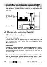
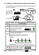
6.3- Display of receiver/receiver module radio channel
This procedure is used to identify the number of the radio channel
used by the receiver.
Step
Actions and states of receiver / receiver module
indicator lights
1
2
3
Switch off the receiver or the transceiver
4
Switch off the receiver / transceiver
Remove jumpers
JP1
and
JP2
Insert jumpers
JP1
and
JP2
Then, switch on the receiver or
the transceiver
The radio channel currently used by the receiver is displayed
by indicator lights
V2
and
V3
V2
indicates the tens, if ON = 10, if OFF = 0.
V3
indicates the units by a number of flashes
V1
V2
V3
V3
V3
V3
Example :
Radio channel :
10 + 3 =
13
, i.e. frequency 434,300 MHz
JP1 JP2 JP3
JP1 JP2 JP3
+
V2
JP1
RM
R1
R2
R3
R4
JP2 JP3
V1
V3
4 5 6 7 8 9 10 11 12 13
1 2 3
JP1
12
3
4 5 6 7 8 9 10 11 12 13
16 17 18 19 20 21
14 15
RM
R1
R2
R3
R4
R5
R6
R7
R8
V2
V1
V3
JP2 JP3
JP1
V2
V1
V3
JP2
JP3
V2
JP1JP2
JP3
V1
V3
Receiver
ISRS
Receiver
ISRA
or
transceiver
receiver module
IST
Summary of Contents for ISIS Series
Page 2: ...2 ISIS 331260D revision02...
Page 52: ...52 ISIS 331260D revision02 FR DE EN...
Page 102: ...102 ISIS 331260D revision02 FR DE EN...
Page 153: ...153 ISIS 331260D revision02...
Page 154: ...154 ISIS 331260D revision02 NOTES...
Page 155: ...155 ISIS 331260D revision02...

