www.jaybeamwireless.com
Page
3/6
E1540-104-00
TRIO Installation
5860903 - 5834903 - 5863903 - 5832903
5860803 - 5834803 - 5863803 - 5832803
5860803G - 5834803G - 5863803G - 5832803G
Fixation
L'antenne est livrée avec 6 boulons de fixation M10 (vis, écrou,
rondelle plate et rondelle contact).
Elle doit être fixée sur le sommet d'un mât comportant les
perçages correspondant à l'interface de fixation. Cette interface
est décrite à la fin de ce document ainsi que le perçage
recommandé pour le sommet du mât.
Il faut installer un boulon de fixation par fente à la base de
l'antenne, en les répartissant régulièrement. La rondelle plate doit
se trouver sous la tête de la vis et la rondelle contact sous l'écrou
avec ses cannelures coté écrou.
Couple nominal de serrage des boulons de fixation : 48 Nm
Orientation
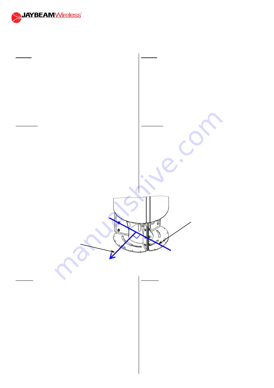
Chacun des 3 secteurs est aisément repérable au niveau de la
zone de service. L'angle entre chaque secteur est fixe et vaut
120° - Il suffit d'orienter un des secteurs pour que les deux autres
le soient.
La direction nominale d'un secteur est la perpendiculaire
K
à la
direction
J
que représente les arrêtes verticales de la zone de
service.
Les fentes à la base de l'antenne permettent de faire tourner
l'antenne sur elle-même. Desserrer légèrement les vis M10 de
fixation pour faire tourner l'antenne dans la direction désirée.
Chaque secteur dispose d'un réglage indépendant de son
orientation de ±15° par rapport à l'installation mécanique (voir
plus bas).
Fixation
The antenna is supplied with 6 M10 bolts (screw, nut, flat washer
and contact washer).
The antenna must be fixed at the top of a mast already prepared
with the holes corresponding to the antenna installation interface.
This interface is described at the end of this document together
with the recommended flange holes at the top of the mast.
It is necessary to use one bolt per slot on the antenna base, with
a regular spacing between them. The flat washer will be under
the screw head and the contact washer will be under the nut with
its grooves facing the nut.
Nominal torque for the bolts: 48 Nm
Orientation
Each of the 3 sectors can be easily located by looking at the
service area. The angle between each sector is fixed at 120° -
once one sector is set to its desired direction, the two other will
also be oriented.
The nominal direction of a sector is the perpendicular
K
relative
to the direction
J
made by the two vertical edges of the service
area.
The slots at the antenna base allow rotating the antenna to set
the sector. Unscrew slightly the M10 screws to rotate the antenna
in the desired position.
Each sector has an independent adjustment of its orientation of
±15° in regards of the mechanical installation (see below).
Bretelles
Les bretelles coaxiales passent par le trou central à la base de
l'antenne. Les former pour qu'elles arrivent au niveau des
connecteurs. respecter le rayon de courbure minimum spécifié
par le fabricant du câble. Serrer les connecteurs au couple
nominal recommandé par le fournisseur des bretelles. les
connexions ne doivent pas appliquer d'efforts latéraux sur
l'antenne ou ses connecteurs, et doivent respecter les
recommandations de l'opérateur.
La polarisation correspondant à chaque connecteur est marquée
sur la bague de couleur entourant chaque connecteur. Les accès
"+45" et "-45" sont interchangeables sauf prescription particulière
de l'opérateur.
Les connecteurs ne doivent pas supporter le poids des câbles
coaxiaux. Des systèmes pour soutenir les câbles doivent être
utilisés dans le mât support de l'antenne TRIO.
Étanchéifier les connecteurs. La compacité de l'antenne ne laisse
pas beaucoup de place pour cette opération, qui doit être faite
soigneusement.
Jumpers
The coaxial jumpers pass through the central hole of the antenna
base. Bend them gently to route them to the connectors. Comply
with the minimum bending radius specified by the cable
manufacturer Attach the connectors to the nominal torque
recommended by the jumpers' supplier. Connection should
ensure that there is no undue stress on the antenna or its
connectors, and shall be in accordance with operator's standard
specifications.
The polarisation related to each connector is marked on the
coloured plastic ring around each connector. The "+45" and the
"-45" coaxial ports are interchangeable unless otherwise
specified by the operator's requirements.
The connectors must not support the weight of the coaxial
cables. Cable supporting devices must be provided in the TRIO
supporting mast.
Seal the connections. The compactness of the antenna does not
provide much room for this operation, which must be carefully
done.
K
90°
J


