background image

Read operator’s manual carefully and 

thoroughly. Understand all safety warnings and

instructions before attempting operation of the unit.

DO NOT OPERATE THE UNIT DRY (

FULL WATER SUPPLY IS REQUIRED 

IN THE SUMP

). Avoid permanent damage to the unit’s sump pump.

Follow all local electrical and safety codes as well as the United States 

National Electrical Codes (NEC) and Occupational Safety and Health 

Act (OSHA).

Always operate SS 700 with it's safety guards and housing securely 

in place.

Disconnect power before inspecting or servicing machine. Hydro 700 

must be properly grounded as a precaution against possible electric 

shock. Check for correct voltage supply.

Keep cord away from heat, oil, sharp edges and moving parts. Replace 

damaged cords immediately. Damaged cords increase the risk of 

electric shock.

If use of an extension cord is necessary, use a heavy, gauge 3 wire 

extension cord with a molded three-prong plug.

Keep hands and all objects from entering the path of the blade.

Install the Hydro SS 700 at bench-top height or higher for added 

safety and optimum performance.

Do not use flammable liquids, caustic materials, or corrosive materials 

with the Hydro SS 700.

When servicing Hydro SS 700, use only identical replacement parts 

and follow instructions in the maintenance section of this manual. Use 

of unauthorized parts or failure to follow maintenance instructions 

may damage equipment or cause personal injury.

GENERAL SAFETY

1.

2.

3.

4.

5.

6.

7.

8.

9.

10.

11.

The 

Hydro SS 700

 uses a high-speed 

component to atomize water, the following 

safety precautions must be observed at all 

times: 

Summary of Contents for Aquafog HYDRO SS 700

Page 1: ...HYDRO SS 700 OPERATOR S MANUAL Read Understand Retain for Future Reference NOTICE BENCH TOP ...

Page 2: ...Notes Purchase Date Model ID Number Vendor Information ...

Page 3: ...p edges and moving parts Replace damaged cords immediately Damaged cords increase the risk of electric shock If use of an extension cord is necessary use a heavy gauge 3 wire extension cord with a molded three prong plug Keep hands and all objects from entering the path of the blade Install the Hydro SS 700 at bench top height or higher for added safety and optimum performance Do not use flammable...

Page 4: ...AN BE AUTOMATED WHEN USED IN CONJUNCTION WITH A CONTROL THE FAN MAY NOT APPEAR POWERED BUT COULD SUDDENLY BEGIN HIGH SPEED ROTATION AS A FUNCTION OF THE PRESET CONTROL WARNING HIGH SPEED ROTATION NEVER OPERATE UNIT WITHOUT THE HOUSING AND SAFETY GUARDS INSTALLED NOTIFICATION GROUND FAULT RECEPTACLES ARE STRONGLY RECOMMENDED AND MAY BE REQUIRED BY LAW NOTICE WARNING ...

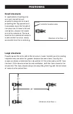
Page 5: ...le level for monitoring Large structures Equally space the units within the structure Lower humidity and or cooling requirements can allow for greater distance between fans Usually the maximum distance between fans should be 20 from the side and 35 from the front If the structure has forced ventilation shift the fans closer to the intake end The fans should always be propelling their fog with the ...

Page 6: ... no ventilation install the unit at the largest most open end and propel the fog towards the opposite end or propel the fog in the direction with natural air flow DO NOT propel the fog into the wind or direction of airflow DO NOT pivot the fogging head to propel fog at a sharp downward angle DO NOT cramp the fan in tight spaces or skinny aisleways DO NOT mount the fan near the ground or underneath...

Page 7: ... the retaining clip and pulling on the tubing See Fig 1 Trim and push tubing back into the connector to secure INSTALLATION or With Control No Control 115V Receptacle Control s Piggyback Pre wired Plug Fig 2 Direct Drain Tubing into the Sump Pull on tubing Hose Connector Push on retaining ring Fig 1 Insert Drainage Line Slip the drain tube into the black fitting leading to the sump box See Fig 2 C...

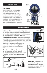
Page 8: ...mp area and nearby the pump If you need to clean inside the pump the cover easily snaps off See Fig 5 Blade s Reservoir Area Water Passageway O ring Stainless Face Plate Blade Assy 3 in 1 oil Oil ports MAINTENANCE Fig 3 OPERATION Switch Box Fog Output After the unit has been plugged in and the water turned on you can adjust fogging output with the quarter turn flow control valve located at the bac...

Page 9: ...rotating shaft back and forth until loose 2 If motor smells doesn t start with a direct power supply or shaft will not loosen up replace motor 3 Sump may not be getting water fast enought Check float valve assembly Check water line pressure and any kinks in water line tubing 4 If sump and float valve checks out good check the sump pump electrically and mechanically replace if needed 5 Remove Feed ...

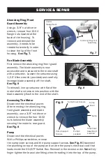
Page 10: ...ard See Fig 8 Pump Disconnect the electrical power With a Phillips screwdriver remove the sump cover screws and the pump support screws See Fig 9 Disconnect the plumbing on top of the pump and un wire the pump s electrical cord that leads inside the ON OFF Switch Box Reinstall in the reverse order Note Only finger tighten the brass tube fitting when threading it into the top of the pump 10 32 Nuts...

Page 11: ... a 620 8 SST Water Feed Tube 400 130 9 Pivot Location NA 10 Sump 400 131 11 Float Valve Assembly 400 012 12 Flow Control Valve 400 016 14 Pump 400 134 15 Pump Bracket 622 17 115V Toggle Switch 109 18 Switch Box 82 19 Switch Box Cover 85 21 Drain Barb Fitting 400 114 22 Drain Hose 400 089 23 1 4 Water Tubing W 14 24 Garden Hose Connect W 2 1 2 5 9 10 7 14 15 12 4 8 11 17 18 19 21 22 23 24 3 6 ...

Page 12: ...or unauthorized repairs or alterations which affect the machine s performance or reliability LIMITATIONS OF LIABILITY TO THE EXTENT ALLOWABLE UNDER APPLICABLE LAW JAYBIRD MANUFACTURING INC S LIABILITY FOR DEATH INJURIES TO PERSONS OR PROPERTY OR FOR CONSEQUENTIAL OR INCIDENTAL DAMAGES ARISING FROM THE USE OF OUR EQUIP MENT IS EXPRESSLY DISCLAIMED JAYBIRD MANUFACTURING INC S LIABILITY IN ALL EVENTS...

Reviews: