1
2
(English)
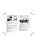
Speaker Function Description
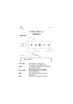
1.1 Power
1.2 Volume (+/-)
1.5 Input
1.3 Mute
1.4 Mode
A. Center Speaker (with build in decoder)
1. Front Panel Control Functions
1.1 Power :
Turns system stand-by power on/off.
1.2 Volume (+/-) :
Raises or lowers the systems volume level.
1.3 Mute :
Mutes/Restores systems volume.
1.4 Mode :
Manual selection of audio modes. Choices are dts, Dolby Digital, Dolby
Pro Logic and Stereo.
1.5 Input :
Manual selection of audio input modes. Choices are Line, Optical, and
Coaxial.
2. Outputs
2.1 OUTPUT :
9 pin DIN jacks for 6 channels analog audio signal output.
2.2 L/R :
3.5mm jack for Front Left and Front Right analog audio signal output.
2.3 CEN/SUB :
3.5mm jack for Center and Sub-Woofer analog audio signal output.
2.4 LS/RS :
3.5mm jack for Left Surround and Right Surround analog audio signal
output.
3. Inputs A : Analog Audio Source
3.1 Line 1 :
Left/Right RCA input jacks for analog stereo audio source.
3.2 Line 2 :
Left/Right 3.5mm input jacks for analog stereo audio source.
4. Inputs B : Digital Audio Source
4.1 Optical :
Optical fiber input for digital audio source (PlayStation 2, DVD player
or device with optical digital output).
4.2 Coaxial :
Coaxial input for digital audio source (DVD player or device with
coaxial digital output).
5. Power Input
5.1 DC IN :
DC power input jack (from DC adapter).
6. Speaker Input
6.1 CEN SPK. IN:
Accepts the CEN output from Subwoofer (B.4 CEN)
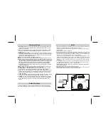
B. Subwoofer (back) Control Functions :
B.1 Power SW :
Turns system power on/off.
B.2 AC IN :
AC Power input cord.
Subwoofer Speaker
(Back)
B.3 Input ( 9 pins DIN jacks) :
Accepts the DIN cable connected to Center
speaker's DIN jack output which is defined by JS especially.
B.4 SPEAKER OUTPUT :
FL/FR :
RCA audio output to Front left and Front right speakers.
SL/SR :
RCA audio output to Rear left and Rear right speakers.
CEN :
RCA audio output to Center speaker.( 6.1 CEN SPK. IN )
B.4 FR
B.4 FL
B.4 SL
B.4 SR
B.4 CEN
B.1 Power SW
B.3 Input(DIN)
B.2 AC IN
2.1 OUTPUT
2.2 L/R
2.3 CEN/SUB
2.4 LS/RS
3.1 Line 1
3.2 Line 2
4.1 Optical
4.2 Coaxial
5.1 DC IN
Center Speaker
(Front)
Center Speaker
(Back)
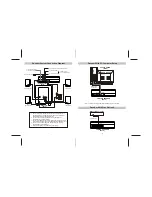
1. Speaker Icons :
Indicate active speakers in different mode. For example, 6
speakers and listener will light on when dts or Dolby Digital mode was selected.
And only listener, left and right speakers are light on when Stereo mode selected.
2. LED Display :
Displays audio mode status.
2.1. 321 = 5.1 Channels (Digital)
2.2. 200 = Stereo (2 Channel)
3. db Symbol :
Will light when using the Volume or Trim adjustment functions.
4. ms Symbol :
mini second, Will light while using the C_Delay or S_Delay
adjustment functions.
5. % Symbol :
Will light when using the Dynamic adjustment function.
6. LOCK :
The Decoder can automatically detect the input signal and audio type.
When both are detected, the lock indicator will light.
7. Mute :
Indicate mute status.
8. ST-BY :
Stand By, indicate LED is normal on when power adaptor has connect to
decoder box.
9. LINE :
LED will light on if input signal comes from line input.
10. OPTICAL :
LED will light on if input signal comes from Optical.
11. COAXIAL :
LED will light on if input signal comes from Coaxial.
12. Dolby Digital :
Dolby Digital audio mode is selected.
13. dts :
Digital Theater System audio mode is selected.
14. Pro Logic :
Dolby Pro Logic audio mode is selected.
15. ST :
Stereo audio mode is selected.
2. LED
1. Speaker Icons
3. db Symbol
4. ms Symbol
5. % Symbol
6. LOCK
15. ST
14. Pro Logic
13. dts
12. Dolby Digital
7. Mute
Indicator Display Lights
8.ST-BY
11. COAXIAL
10. OPTICAL
9. LINE
6.1 CEN SPK. IN
Summary of Contents for J-9941B
Page 7: ...61 ...

