background image


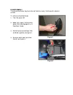
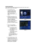
Remove shroud, by removing t
two screws located on the top 
front of the black pane

7. 

he 

l.  Lift the 

shroud, see figure 7. 

8. 


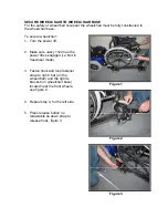
the powered base, see 

figure 8. 

9. 

ount and 

remove, see figure 9. 


Remove cotter pin connecting the
mount to 


Lift wheelchair base m


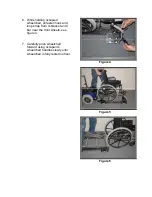
Figure 7 


Figure 8 


Figure 9 


Summary of Contents for 1122

Page 1: ...Jazzy 1122 Wheelchair Trainer Owner s Manual ...

Page 2: ...his system To operate keyed ignition 1 Insert key into ignition slot see Figure 1 on the right 2 Turn 90 degrees to the right until green light indicator turns on see Figure 2 on the right 3 To turn off turn 90 degrees to the left until green light indicator turns off WARNING Key should not be removed when operating in motion Key can only be removed in the OFF position Figure 1 Figure 2 ...

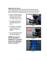
Page 3: ...ld three prong connector with large prong on top and two smaller prongs on bottom 2 At an angle push button on trainer down with connector and slide into place See Figure 1 3 Disengaging To stop trainer in motion pull on the tether cord until connector un attaches from trainer See Figure 2 4 When disengaged blinking red light near keyed ignition will be visible See Figure 3 WARNING Emergency Kill ...

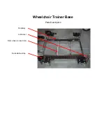
Page 4: ...Wheelchair Trainer Base Parts Description U Bracket Frame base cross bars Roadway Retractable strap ...

Page 5: ...2 Make sure Jazzy 1122 has the power drive engaged i e Not in freewheel mode 3 Align the wheelchair base mount to the custom mount of the Jazzy1122 see figure 1 4 Insert cotter pin to connect Jazzy 1122 to wheelchair base see figure 2 5 Connect plug into the controller see figure 3 6 Wheelchair trainer is ready to operate Figure 1 Figure 2 Figure 3 ...

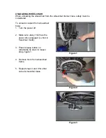
Page 6: ...for elevator access To remove wheelchair base 1 Turn the power off 2 Make sure Jazzy 1122 has the power drive disengaged i e in freewheel mode 3 Disconnect powered base from controller joystick see figure 1 4 Remove both cotter pins from mount see figure 2 Figure 1 Figure 2 ...

Page 7: ...5 Move wheelchair trainer forward to remove see figure 3 and 4 6 The Jazzy 1122 base can now be maneuvered by the controller see figure 5 Figure 3 Figure 4 Figure 5 ...

Page 8: ... off 2 Make sure Jazzy 1122 has the power drive engaged i e Not in freewheel mode 3 Fasten hook and loop fastener strap to right I bar on the wheelchair and the right U bracket on wheelchair base located near the front wheels see figure 2 4 Repeat step 3 for the left side 5 Press release button on retractable tie down strap to release hook figure 3 Figure 1 Figure 2 Figure 3 ...

Page 9: ...pant s wheelchair see figure 4 7 Manually tighten retractable tie downs see figure 5 CAUTION DO NOT OVER TIGHTEN 8 Make sure there is enough tension on strap see figure 6 9 Repeat step 5 8 for the left side 10 Check that chair is completely secure Figure 4 Figure 5 Figure 6 ...

Page 10: ...11 The chair is now completely secured figure 7 Figure 7 ...

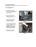
Page 11: ...tion on base connection 3 Ensure the power drive is engaged on the Jazzy 1122 i e Not in freewheel mode 4 Align Wheelchair base and occupants wheelchair in a straight line see figure 1 5 Put one foot between frame of base and roll wheelchair base along the roadway of the wheelchair trainer see figure 1 CAUTION Do not step on frame of wheelchair base 6 Grasp handle of occupants wheelchair see figur...

Page 12: ...7 Gently roll occupied wheelchair up onto the base lifting the rear wheels and then the front wheels onto the roadway Figure 3 Figure 4 ...

Page 13: ... occupant from wheelchair base 1 Turn the power off 2 Make sure Jazzy 1122 has the power drive engaged i e Not in freewheel mode 3 Press release button on retractable tie down to loosen strap figure 1 4 Remove hook from wheelchair frame 5 Repeat steps 3 and 4 for other side of wheelchair base Figure 1 Figure 2 Figure 3 ...

Page 14: ... unfasten hook and loop strap from U bracket and I bar near the front wheels see figure 4 7 Carefully push wheelchair forward using occupant s wheelchair handles slowly until wheelchair is fully rested on floor Figure 4 Figure 5 Figure 6 ...

Page 15: ...lchair as needed To make conversion to a Jazzy 1 Turn the power off 2 Open electrical compartment shroud see figure 1 3 Remove control harness plug see figure 2 4 Remove controller joystick from mount and tread controller cable through controller mount holder see figure 3 Figure 1 Figure 2 Figure 3 ...

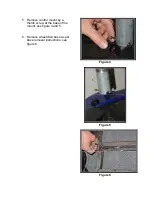
Page 16: ...5 Remove control mount by a thumb screw at the base of the mount see figure 4 and 5 6 Remove wheelchair base as per base removal instructions see figure 6 Figure 4 Figure 5 Figure 6 ...

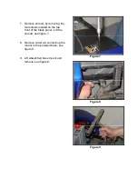
Page 17: ...ews located on the top front of the black pane 7 he l Lift the shroud see figure 7 8 the powered base see figure 8 9 ount and remove see figure 9 Remove cotter pin connecting the mount to Lift wheelchair base m Figure 7 Figure 8 Figure 9 ...

Page 18: ...footrest footrest mount to Jazzy 1122 base see figure 10 and 11 11 Replace shroud and two screws 12 Assemble the controller and seat following the Jazzy 1122 owner s manual section IV Figure 10 Figure 11 Figure 12 ...

Page 19: ...13 Conversion completed see figure 14 Figure 13 Figure 14 ...

Page 20: ... See base connection section 4 Lift front of the wheelchair base and use this as a handle to maneuver the Jazzy 1122 to a proper storage location see figure 1 and 2 5 For additional safety engage the Jazzy 1122 powered drive i e Not in freewheel mode 6 The wheelchair trainer can now be stored until needed by leaning the wheelchair base against the Jazzy 1122 base see figure 3 7 Secure wheelchair b...

Page 21: ...evice the whole unit should be OFF 1 Power OFF from Joystick 2 Place key ignition to the OFF position 3 Snap the Power connector see figure 1 4 Connect the green RC connector to the green label see figure 2 5 Connect both red and blue RC jacks to the appropriate color code labels on the Joystick side see figure 3 and from the Communication Device see figure 4 on the next page Figure 1 Figure 2 Fig...

Page 22: ...unt the IR Receiver Module to a Communication Device 7 Turn the key switch to the ON position 8 Power ON Jazzy 1122 power button located on the Joystick WARNING Safely warp louse wires away from user and moving parts 9 If indicators are free of errors operate like normal Figure 4 ...

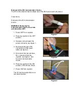
Page 23: ...m Joystick 2 Place key ignition to the OFF position 3 Squeeze and pull apart the power connector see figure 1 4 Disconnect the green RC connector from the green label see figure 2 5 Disconnect the red and blue RC connectors from the Joystick see figure 3 and from the communication device 6 Place key ignition to the ON position LED will turn Green 7 Power ON from Joystick The IR Communication Devic...

Page 24: ...remove the Batteries 1 Once shell is remove disconnect Anderson connectors see figure 1 and 2 CAUTION When removing batteries watch out for wires and parts A good snag can damage parts or rip wires out See figure 3 WARNING PULL FROM HANDLES ON BATTERY 2 Remove Batteries straight up See figure 4 Figure 1 Figure 2 Figure 3 ...

Page 25: ...out See figure 1 1 See bottom of main unit to place appropriate Gel battery Place appropriate Gel Battery straight in arrows pointing out WARNING Tuck away all wire from moving parts 2 Locate the appropriate color coated Anderson connectors see figure 4 3 Attach the Anderson connectors by firmly pushing connectors together see figure 5 4 Attach shell see section to install shell in the Wheelchair ...

Page 26: ...ase do not push the base of the Jazzy 1122 by the control bar see figure 1 The control bar is not a structural member WARNING Do not step on the cross bars of the wheelchair trainer see figure 2 Figure 1 Figure 2 ...

Page 27: ...eing applied to the batteries Check to make sure batteries are being charged See Ammeter on left side of Figure 1 3 Fuses Your wheelchair trainer is equipped with two fuses a The red fuse is used for charging and basic chair operations b The clear fuse is used for the ignition communication system and kill switch If incorrect operation is occurring change fuse with new identical fuses See Figure 2...

Page 28: ...Notes ...

Page 29: ...Notes ...

Reviews: