background image

ENGLISH  

OPERATION 

MANUAL 


JB SYSTEMS 

5/30 

BEAT4 Mk2 

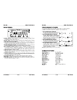
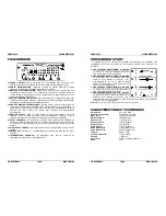
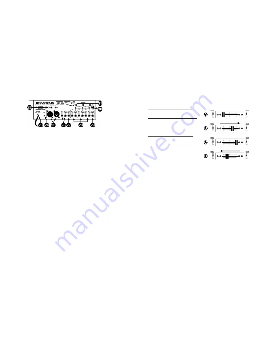
REAR PANEL 


22. FADER  CONTROL:

 When connected to these inputs, compatible CD-players can be 

controlled by the fader starts of this mixer.  

23. MAINS  CABLE: 

connect this cable to a 230V/50Hz mains outlet. Before use, inspect 

the cable to be sure it’s not damaged! 

24. GROUND  (GND)  CONNECTION: 

Many Turntables have a GND-connection. It is 

preferable to connect this signal ground to the GND-connector. If your turntable does 
not have a ground wire, you don’t have to use this connector. 

25. MASTER1  BALANCED  OUTPUT:

 The XLR-connectors can be used to connect this 

mixer to any balanced amplifier input, using special balanced signal cables. 

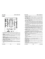
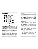
26. MASTER  UNBALANCED  OUTPUTS:

 The “mast.1” output has the same output signal 

as the balanced master output(25) but unbalanced. The “mast.2” output carries the 
same signal but can be controlled independently by the master2 level (20). Use the 
outputs to connect unbalanced amplifiers. 

27. RECORD  OUTPUT: 

Carries the same signal as the master outputs but is not 

influenced by the master level, balance and mono/stereo controls. Used to connect 
analog recording equipment. 

28. INPUT  CHANNELS: 

each used to connect two different line level audio signals. Refer 

to switch (31) to change one line input to phono level. The input source selector (2) on 
the front determines which input will be active. 

29. LINE INPUT CHANNEL1:

 used to connect a line level audio signal to channel1.  

30. MIC  INPUT:

 ¼” mono jack alternative to the XLR microphone input on the front (1). 

31. PHONO/CD  SWITCH:

 This switch makes it possible to switch between the CD and 

phono level inputs on channels 2, 3 and 4. 


ENGLISH  

OPERATION 

MANUAL 


JB SYSTEMS 

6/30 

BEAT4 Mk2 

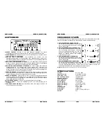
CROSSFADER STARTS 

The crossfader integrates the optical fader start switches. These fader starts are 
compatible with all current JB Systems CD-players. This is how it works: 
 

A.  CROSSFADER IN LEFT POSITION:


CD-player connected to fader start connector 
1 is playing, the other CD-player is paused. 

B.  CROSSFADER MOVES TO THE RIGHT:


CD-player connected to fader start connector 
1 stops playing, returns to its previously 
programmed cue point and waits in pause. 
The other CD-player starts playing from its 
previously programmed cue point. 

C.  CROSSFADER IN RIGHT POSITION:


CD-player connected to fader start connector 
2 is playing, the other CD-player is paused. 

D.  CROSSFADER MOVES TO THE LEFT:


CD-player connected to fader start connector 
2 stops playing, returns to its previously 
programmed cue point and waits in pause. 
The other CD-player starts playing from its 
previously programmed cue point. 

Important:

 Both fader start switches must be in “ON” position! 


SPECIFICATIONS 

Power Supply: 

AC 230 V, 50Hz 

Frequency response: 

20-20.000Hz (+/-2dB) 

THD + noise:


<0.09% @ 1kHz, 0dB 

S/N Ratio (IHF-A):


>86dB @ 1kHz. 

Micro inputs: 

1.5mV @ 10k


Line/CD inputs: 

150mV @ 22k


Phono inputs: 

3mV @ 47k


Record output: 

775mV @ 600


Master A/B output: 

1.5V @ 4k7

 unbal. 

Master A/B output: 

850mV @ 600

 bal. 

Talkover: 

0dB 

Æ

 -15dB 

Tone controls: 

+12dB / -26dB 

Headphone: 

1.5V@33


Dimensions:


294(W) x 370(H) x 95(D) mm  

Weight:

 5kg

Summary of Contents for BEAT 4 Mk2

Page 1: ...zing Bedienungsanleitung Manual de instrucciones Version 1 0 The Power Source for DJ s WWW BEGLEC COM Copyright 2004 by BEGLEC cva Reproduction or publication of the content in any manner without expr...

Page 2: ...ts or spill liquid inside the turntable Electric shock or malfunction may result INSTALLATION GUIDELINES Install the unit in a well ventilated location where it will not be exposed to high temperature...

Page 3: ...udio sources so the beats will be nicely synchronized When the synchronization becomes better the yellow LEDs will turn on Finally when both beats are in perfect sync the green led in the center turns...

Page 4: ...signal to channel1 30 MIC INPUT mono jack alternative to the XLR microphone input on the front 1 31 PHONO CD SWITCH This switch makes it possible to switch between the CD and phono level inputs on cha...

Page 5: ...m talliques et ne pas verser de liquides dans l appareil Il pourrait en r sulter des lectrocutions ou des dysfonctionnements CONSEILS D INSTALLATION Installer l appareil dans un lieu bien a r l abri d...

Page 6: ...devrez adapter la vitesse des sources audio connect es pour bien synchroniser les beats Quand la synchronisation s am liore les LEDs jaunes s allumeront Finalement quand les deux beats sont parfaiteme...

Page 7: ...ur la face avant d termine quelle source sera activ e 29 LINE INPUT CHANNEL1 est utilis pour connecter un signal audio du type Line au canal 1 30 ENTREE MIC mono jack une alternative pour l entr e mic...

Page 8: ...kken of slechte werking kunnen het gevolg zijn INSTALLATIEVOORSCHRIFTEN Plaats de mengtafel in een goed geventileerde ruimte waar zij niet blootgesteld is aan hoge temperaturen of vocht Het plaatsen e...

Page 9: ...roniseerd worden Wanneer de synchronisatie beter wordt zullen de gele LEDs aangaan Wanneer beide beats uiteindelijk perfect synchroon zijn zal de groene LED in het midden aangaan U kunt nu de beat van...

Page 10: ...activeerd zal worden 29 LINE INGANG KANAAL1 sluit hier een lijngeluidssignaal aan op kanaal 1 30 MICRO INGANG mono jack ontdubbeling van de XLR microfooningang op de voorzijde 1 31 PHONO CD SCHAKELAAR...

Page 11: ...etzen Sie dieses Ger t niemals N sse und Feuchtigkeit aus Stellen Sie keine Beh lter mit Fl ssigkeiten in die N he des Ger tes es ist nicht wasserdicht und k nnte besch digt werden INSTALLATIONSANLEIT...

Page 12: ...uchten sind die beiden Musiktitel aus dem Takt Beachten Sie bitte das man nur Musiktitel ineinander mixen kann wenn diese ann hernd ber die gleiche Geschwindigkeit gemessen in Beats pro Minute verf ge...

Page 13: ...Pegel von diesen unbeeinflusst Schlie en Sie hier Ihr Aufnahmeger t an 28 EINGANGSBUCHSEN F R DIE KAN LEN An jeden Eingang k nnen zwei verschiedene Linequellen angeschlossen werden Mit dem Wahlschalte...

Page 14: ...mantenimiento importantes en el manual que acompa a este producto Para evitar riesgos de electrocuci n o incendio evitar la exposici n a la lluvia o humedad No insertar objetos metalicos ni dejar caer...

Page 15: ...te desincronizados el LEDs rojo se encender Usted deber adaptar la velocidad de las fuentes audio conectadas para sincronizar bien el beat Cuando la sincronizaci n se mejore el LED amarillo se encende...

Page 16: ...er acelerada 29 LINE INPUT CHANNEL1 es utilizado para conectar una se al audio del tipo Line al canal 1 30 ENTRADA MIC el jack 1 4 es una alternativa para la entrada XLR situada en el frontal 1 31 INT...

Reviews: