background image

1

2

3

4

5

6

7

8

9

10

11

12

13

14

15

16

17

18

19

20

M

L

K

J

I

H

G

F

E

D

C

B

A

FOLIO

DESSINE PAR:

DATE:

27/03/2005

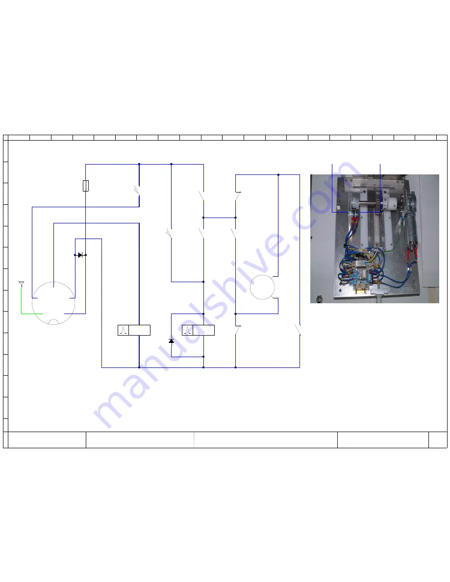
Option système crochets

Hanger feeder option

JH

14

Système à crochets

Hangers system

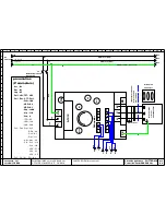
Plug:Option Hanger(crochet)

3

2

1

4

5

SW1

(top switch)

SW2

(Bottom swtich)

R1

R2

R2

R2

R2

R2

R1

R2

MH1

CR1

FC1 : T1A Temporise

SW1

SW2

C

R

2

D-

C+

A2

A1

A2

A1

22

21

12

11

31

34

14

11

21

24

11

14

D-

C1

C1

D-

C3

D-

C5

C4

C2

C2

C+  ( fil N° 2 )

PE

-

+

X

1

6


fi

N

°1

 )

D

 (

 f

il 

N

°3

 )

B

Y

1

 (

 f

il 

N

°4

)

DESSINE PAR:

B

Y

1

 (

 f

il 

N

°4

)

DATE:

C+  ( fil N° 2 )

5

4

3

PE

2

M

X

1

6


fi

N

°1

 )

1

27/03/2005

Option système crochets

Hanger feeder option

JH

14

Système à crochets

Hangers system

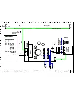
Plug:Option Hanger(crochet)

3

5

2

4

1

R1

17

11

18

19

20

R2

6

L

R2

K

J

R2

14

C1

C1

C+

D-

R2

15

16

R2

12

-

+

D-

D-

D-

11

C2

C3

C2

C4

C5

R1

A2

13

A1

14

FC1 : T1A Temporise

14

11

34

31

24

21

21

22

CR1

SW1

7

SW2

8

MH1

9

10

R2

A2

11

A1

12

FOLIO

A

C

R

2

B

C

SW1

(top switch)

D

E

SW2

(Bottom swtich)

F

G

H

I

D

 (

 f

il 

N

°3

 )

JAMES BURN International

Wob3500IIMK2 version 200-240 Vac 

AFFAIRE N°0305ER-0D      50/60Hz

Summary of Contents for Wire-O WOB3500 MK2

Page 1: ...ding Machine Wire O Lhermite and UniCoil are registered Trademarks of James Burn International Patent Pending Operating Instructions Mod le WOB3500 MK2 Version 200 240Vac 50 60Hz Single phase Issue 2...

Page 2: ...Installation of your binding machine 2 10 Choosing a location for your binding machine 2 10 Floor plan 2 10 Power points 2 10 Unpacking your binding machine 2 10 Unpacking your binding machine contin...

Page 3: ...7 11 Technical data about your binding machine General data 11 29 Machine performance 11 29 Electrical data 11 30 Protection devices fuses 11 30 12 Amendments Issue no 1 12 31 13 Warranty James Burn I...

Page 4: ...ven personal injury This manual is a necessary and permanent part of your binding machine Always return the manual to its pocket holder on the machine Note This manual gives you general guideline for...

Page 5: ...roperty damage The manual uses the words DANGER WARNING CAUTION and NOTICE to accompany the safety alert symbol The words are defined as follows DANGER You will cause severe personal injury or death i...

Page 6: ...screw driver or bar to clear jams in the Closing Head Serious injury may occur if your fingers come into contact with the closing tools while the machine is operating NEVER PERFORM ANY REPAIR OR MAIN...

Page 7: ...E THE BINDING MACHINE IF THE GUARDS ARE NOT IN PLACE All guards MUST be in place before you start the binding machine DO NOT ADJUST THE GUARD OPENINGS WHILE THE MACHINE IS SWITCHED ON Servicing must n...

Page 8: ...s machine weighs 277kg 610lbs Never try to lift equipment that is heavier than the maximum rating of your lifting device A minimum of 2 people is required when moving this machine The correct pallet a...

Page 9: ...er handy Keep emergency numbers of doctors ambulance services hospitals and the fire department handy Acquaint yourself with the company fire procedure A NOTE TO ALL EMPLOYERS Know your responsibiliti...

Page 10: ...THIS MANUAL WITH THE BINDING MACHINE This manual is an important part of your binding machine Always keep this manual where it belongs with the binding machine IF YOU NEED THIS MANUAL IN ANY OTHER LAN...

Page 11: ...ing Machine Safely WOB3500 MesDocuments Corinne Notices WOB3500 Anglais 9 Warning Signs on your Binding Machine Identification Plate 2 Adjustable feet to keep the machine steady Adjusting square paper...

Page 12: ...n for your Binding Machine You should choose a site within the office that is solid level and rigid enough to keep the machine accurately aligned even while it is running and place it in a position wh...

Page 13: ...wise it may fall causing property damage and or personal injury Therefore when you are moving the machine check that it is stable The machine weights 277Kg 610lbs Unbolt the retaining straps holding t...

Page 14: ...to VDE 0110 Discharge Current to Potential Earth 3 5mA Protection Measures Against Short circuit Over voltage Motor over temperature and Over current Type of Protection IP20 Electrical Installation I...

Page 15: ...to 9 16 and wire size 6 corresponds to 3 8 The size of the wire required is obtained in the following manner Using the Following Formulae Imperial All 3 1 Pitch Wire Size Book Thickness in inches 1 1...

Page 16: ...16 7 11 1 7 16 3 1 9 5 3 8 8 12 7 3 1 11 0 7 16 9 14 3 9 16 3 1 12 5 10 16 0 5 8 2 1 14 9 16 12 19 0 2 1 16 0 5 8 14 22 0 7 8 2 1 19 0 16 25 4 1 2 1 22 0 7 8 18 28 57 1 1 18 2 1 25 3 1 20 31 8 1 2 1 2...

Page 17: ...een Spool and Cut Lengths Cut Lengths should only be selected if you are using Wire O in cut lengths supplied by James Burn International Select the wire o size see chart page 14 select the number of...

Page 18: ...initialization Return to the previous screen In case of spool without hanger option In case of spool with hanger option In case of cut lengths with hanger option In case of cut lengths without hanger...

Page 19: ...Carefully remove the spool from the shipping carton and remove the protective film Ensure that the wire spool is aligned as shown in the photo below Pull the spool cart out fully Turn the spool suppor...

Page 20: ...til you feel drive cam pin engages in the spool Important push the spool end cap in further so that the cup hole engages into the groove of the spool shaft Next carefully remove the plastic packing cl...

Page 21: ...left hand With your right thumb press the cart return clip Push the assembly back into the WOB3500 Wire being correctly fed from the spool Pushing the cart fully home Important Allow the wire to sit i...

Page 22: ...small loop of the wire on the top Take the end of the wire element and feed it up to the bottom wheel of the wire feed drive Operate the spring loaded switch upwards The wire feed motor will start to...

Page 23: ...a cut length of the requested length to the insertion area if spool selected Pressing the footswitch a second time will move the book block into the closing head where it will be bound Pressing the fo...

Page 24: ...the number of loops of each cut length Select the number of cut lengths Select the length of the jump required in number of loops Validate your choice Launch the cycle by depressing on the pedal or by...

Page 25: ...hangers Unwind slightly the hanger spool up to the beginning of the hangers stock Place the 2 lower stick rules inside the hangers stock up to the little roller Place the 2 stick rules on the little...

Page 26: ...any maintenance work switch OFF the machine and disconnect the electrical supply from the mains supply Daily Maintenance The following daily maintenance is required Brush off loose wire coatings and...

Page 27: ...HT4065A3R1360 24 Vcc 1 Off JE22041 detector OMRON E3T SL33 24 Vcc 1 Off JE22052 inductive detector M30 SICK 1 Off JE29065 Sanyo card 1 Off JE07067 contactor 12A LC1 D12BL 24 Vcc 2 Off JE06076 microswi...

Page 28: ...ual are in a legible condition Failure to do so could result in you being responsible to whom you sell or transfer your binding machine should it cause personal injury or damage to property Disposing...

Page 29: ...hen machine cycles No motor drive Check fuses FC3 FC4 FC6 of the 24Vcc card Check wire lift motor Book transport belts fail to move when machine is cycled No motor drive Check fuses F3 on M5 Inverter...

Page 30: ...nds Switch ON power Initialise the machine NOTA the closing head is on top position and the wire is ejected at the reception 10 2 Error messages Cover open Emergency stop off M9 alarm M8 alarm M6 alar...

Page 31: ...175m Max depth 0 73m Gross weight 277Kg nett 610 lbs nett Base fitting Lockable swivel castors Machine setting Simplistic touch screen controls with fully automatic adjustment no tool changing Machin...

Page 32: ...s Fuse ratings Fuse ID Size and type Europe 230V USA 110V Protections QF1 Circuit breaker 16 Amp 16 Amp Fitted on the main plug GB F2 2x5x20mm time delay T 3 Amp 6 3 Amp Transformer folio 01 12E F3 2x...

Page 33: ...N 1 New operators manual for WOB3500 Issue 1 DB Aug 2004 WOB2 001 2 Program modification PLC screen for wire n 18 n 20 Optional bar on closing jaw for wire n 18 n 20 DB Jan 2009 WOB2 202 2 Replacement...

Page 34: ...rning the defective parts to JBI SAS as well as the cost of reinstalling the replacement or repaired part IN NO EVENT SHALL JBI SAS BE LIABLE FOR LOSS OF USE LOSS OF REVENUE OR LOSS OF PRODUCT OR PROF...

Page 35: ...13857 2008 Safety distance EN ISO12100 1 2004 Safety of machinery Analysis EN ISO12100 2 2004 Safety of machinery Estimate EN ISO13850 2008 Equipment of Emergency stop EN 61000 6 3 2002 Emission of el...

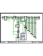
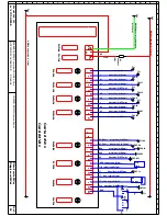
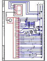
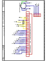
Page 36: ...n platine Electrical Cabinet Settling 13 17 03 2005 Option syst me crochets Hanger feeder option 14 FOLIO DESCRIPTION DATE IND MODIFICATION DATE IND MODIFICATION DATE ECH DATE RESP DES CLIENT JAMES BU...

Page 37: ...vert jaune green yellow 312 AWG16 red 107 D Y16 AWG16 S 1 31mm noir black AWG16 S 1 31mm noir black F4 NV6 111 B A Wob3500IIMK2 version 200 240 Vac AFFAIRE N 0305ER 0E 50 60Hz 17 05 2006 T4A LV5 112 F...

Page 38: ...16 F07 17 34 jaune 35 vert 30 37 37 30 blanc blue S 0 8mm 37 37 vert F01 13 F01 13 F04 16 F07 17 34 brun X20 C F03 12 16 F O F04 16 22 Byo Byo SS1 sur Plc F05 05 SBAU1 F04 15 X21 RS1 ESM BA3 42 34 24...

Page 39: ...ue blue S 0 8mm DS4 bleue blue S 0 8mm CS1 bleue blue S 0 8mm C bleue blue S 0 55mm DS2 bleue blue S 0 8mm R1 F06 12 F11 F06 07 F06 08 F11 F02 05I F06 11 F11 F06 17 F06 17 F11 F02 FC9 F5A FC8 F5A FC7...

Page 40: ...ow A U 1 wire adjust OUT wire adjust IN Init wire adjust XB1 XB1 XB1 XB1 XB1 XB1 XB1 XB1 XB1 XB1 XB1 XB1 XB1 XB1 ZB1 XB1 XB1 XB1 XB1 Vert jaune Gris Blanc XB1 Vert Jaune Marron Masse XB1 Gris Blanc XB...

Page 41: ...401 5 Vdc sens M3 adjust wheel sens M4 adjust bind 23 C F11 F11 F11 F11 F11 F02 07 2 3 4 5 1 Plug Option Hanger crochet F10 15J R22OoHms F06 10 Plc FX1N 40MT DSS24Vcc PNP PLC1 OUTPUT sorties F06 05 B...

Page 42: ...09 CWM4 CWF4 400 400 400 Carte Sanyo JE29065 CN2 CN1 CN3 0 ON OFF ACD1 ACD2 EORG EX1 EX2 EX3 F R LV 1 1 DSW1 1 DSW1 400 400 400 400 Y7 Y03 Y6 Y2 Y5 Y4 Moteur pas pas Step motor orange vert LV F R EX3...

Page 43: ...ow jaune D PE R1C 15 Com 16 AI1 17 5V DESSINE PAR A01 C L01 F11 CL0 C Com F11 LI1 X11 LI2 F04 11 LI3 Y10 LI4 F05 12 24V AWG16 vert jaune green yellow PE AWG16 noir black W AWG16 noir black V U 1 10 PE...

Page 44: ...12 F09 02 PE F09 02 F09 02 13 14 15 16 PE 17 18 19 vers folio 07 20 AWG16 vert jaune green yellow AWG16 noir black AWG16 noir black 20 M L K J I H G F E D C B A 09 11 2009 c ble blind 4x S 0 55mm Norm...

Page 45: ...m Norme UL CSA CE Armoured cable D 112 L01 V CL0 PE Com A LI1 U LI2 Moteur 3 belts M5 3 courroies P 0 025Kw 220Vac LI3 Wob3500IIMK2 version 200 240 Vac AFFAIRE N 0305ER 0E 50 60Hz LI4 JAMES BURN Inter...

Page 46: ...360 SLP 110 STA 14 TFR 65 UFR 70 param tres Parameters 8 9 10 11 12 13 14 15 16 17 18 19 20 M PE L K J vers folio 09 20 AWG16 vert jaune green yellow AWG16 noir black AWG16 noir black c ble blind 4x S...

Page 47: ...ind 4x S 0 55mm Norme UL CSA CE Armoured cable NV5 NV5 LV5 LV5 JAMES BURN International AI1 Y16 5V D A01 1 L01 2 CL0 3 Com 4 LI1 5 LI2 6 LI3 7 LI4 8 24V 9 PE 10 W 11 V 12 U 13 14 PE 15 16 17 18 19 20...

Page 48: ...er YB1 Terminal 111 Bornier XB2 Terminal C 400 D 401 Y16 12 Bornier YB1 Terminal Bornier XB2 Terminal 111 112 103 104 22 C C D 401 400 JH Bornier Terminal XB2 YB1 17 03 2005 Y16 DATE DESSINE PAR FOLIO...

Page 49: ...5 JE07067 T1 folio 01 09 JE08013 FR2 folio 01 09 JE15054 10 Wob3500IIMK2 version 200 240 Vac AFFAIRE N 0305ER 0E 50 60Hz JAMES BURN International DATE 09 11 2009 JH YB1 folio 11 Implantation platine E...

Page 50: ...C4 C2 C2 C fil N 2 PE X16 fil N 1 D fil N 3 BY1 fil N 4 DESSINE PAR BY1 fil N 4 DATE C fil N 2 5 4 3 PE 2 M X16 fil N 1 1 27 03 2005 Option syst me crochets Hanger feeder option JH 14 Syst me crochet...

Reviews: