background image

JBL DA850 DA1650 Owners Manual | rev1.2 Draft20231009 

Pg 9 of 16


©2023 Harman International | Features, Specifications, and Appearance subject to change without notice. 


Speaker outputs provide connection for: 

  Up to four pair of stereo speakers (eight speakers total) to the DA850 

  Up to eight pair of stereo speakers (sixteen speakers total) to the DA1650 

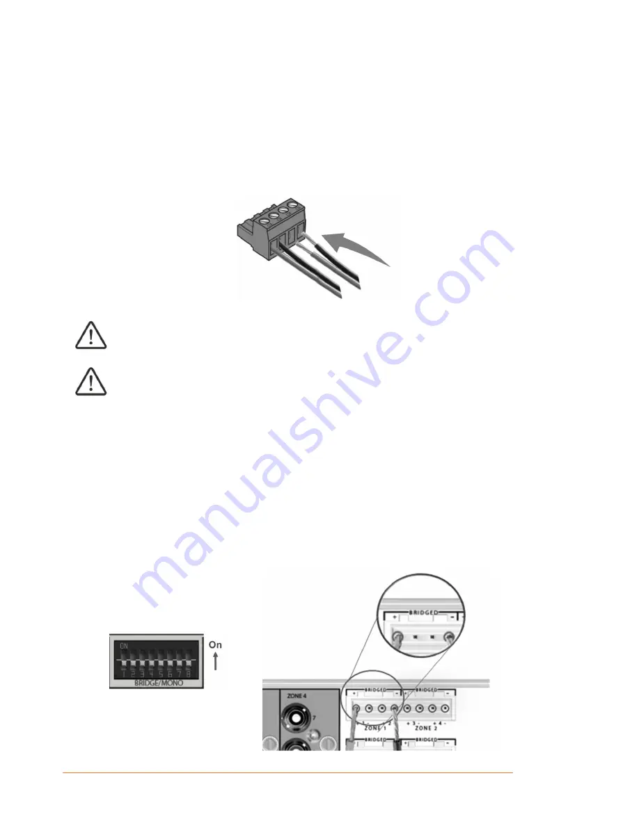
Connection to speakers is provided via phoenix-type connectors that accept bare wire terminations. The 
connectors are grouped in pairs with one connector each for pair. Each pair consists of four wire 
terminations: positive (+) and negative (–) for the Left channel and positive (+) and negative (–) for the 
Right channel. To attach speaker cables to the phoenix connector, strip approximately ¼” of insulation off of 
the end of the positive and negative leads of the cable and insert the bare ends into the corresponding 
position of the phoenix connector, tightening the screw terminals on top to secure the termination. Repeat 
this procedure for each speaker. 


Do not connect the L – and R – (negative) terminals together. Doing so will result in a fault 
condition and the amplifier will either shut down or not work properly.  

Check the polarity of the speakers and wires prior to connecting to the amplifier.  


CONNECTING BRIDGED OUTPUTS 

1.  Set BRIDGE/MONO as needed for each zone by moving the switch to the UP position for that zone. 
2.  Connect the + terminal from the speaker to the + terminal of the left channel on the amplifier. 
3.  Connect the – terminal from the speaker to the – terminal of the right channel on the amplifier.  

The two terminals for a bridged pair of speakers are marked by + BRIDGED –  

In Bridge mode, the pair of amplifier channels in a zone combine to make a mono output of double the 
power. When in bridge mode the left and right channel RCA inputs to the zone are active so you can 
connect one mono source (Left) or a stereo source (Left and Right) which will sum-to-mono 
appropriately.  


Summary of Contents for DA850

Page 1: ...Owners Manual Rev 1 2 Draft20231009 2023 Harman International Features Specifications and Appearance subject to change without notice DA850 DA1650 Distribution Amplifiers...

Page 2: ...rview 4 Rear Panel Overview 5 Installation 6 Rack Mounting 6 Surface Mounting 7 Hardware Setup 8 Connecting Audio Inputs 8 Wiring Output Connnectors 8 Connecting The AC Power Cord 10 Setting Power Mod...

Page 3: ...d to the industry s highest quality standards and offer system integrators with the core features and fundamental connectivity for home audio distribution Please take the time to study the owner s man...

Page 4: ...a fault the LED will blink RED indicating the presence of a short or some other problem related to that channel pair 2 STANDBY BUTTON Activates and deactivates standby mode when the amplifier is conn...

Page 5: ...nal DA series amplifiers or other components that need to mimic the amplifier s power state 6 GLOBAL OUT Provides a line level RCA connector loop pass thru output for connecting multiple DA amplifiers...

Page 6: ...t included Installing a DA series amplifier in a rack 1 Attach the rack ear brackets to the sides of the amplifier using the provided machine screw fasteners into the threaded holes 1 0 1Nm recommende...

Page 7: ...hout notice SURFACE MOUNTING You can also place a single amp on a solid stable surface utilizing the provided feet and fasteners Once positioned ensure the sides of the amplifier are well ventilated a...

Page 8: ...rol Note that for BRIDGE MONO operation a stereo input will be appropriately summed to mono and outputs can be used in either Bridge outputs or single channel pairs WIRING OUTPUT CONNNECTORS Before ma...

Page 9: ...of the phoenix connector tightening the screw terminals on top to secure the termination Repeat this procedure for each speaker Do not connect the L and R negative terminals together Doing so will re...

Page 10: ...indicators light RED reduce the source level until the Clip LEDs no longer light IMPORTANT Always turn off the amplifier by using the rear AC mains rocker switch and disconnect the power cord before...

Page 11: ...de the front panel standby button operation To install a trigger cable Power the controlling source and DA amplifier off Connect the trigger cable to the controlling source and the DA amplifier After...

Page 12: ...atch zones in an installation When turned fully clockwise the output level is at maximum The CLIP indicator LED is located below the Level control If clipping is present while playing an input source...

Page 13: ...2 channels driven 0 5 THD max Rated Power 8 50W Rated Power 4 110W Rated Power 8 Bridged one zone driven 185W Performance Frequency Response 20Hz 20kHz 0 5dB at 1 8th power all loads THD N max at rat...

Page 14: ...riven 0 5 THD max Rated Power 8 50W Rated Power 4 110W Rated Power 8 Bridged one zone driven 185W Performance Frequency Response 20Hz 20kHz 0 5dB at 1 8th power all loads THD N max at rated power 20 2...

Page 15: ...low frequency noise is one of the most common problems within audio video systems This problem even when the volume is at a low level is usually caused by a common problem known as a ground loop A gro...

Page 16: ...2 London Road Apsley Hemel Hempstead Hertfordshire HP3 9TD United Kingdom 2023 Harman International Industries Incorporated All Rights Reserved JBL is a trademark of Harman International Industries I...

Reviews: