background image

3

www.jbl.com

E

ng

lis

h

mOunting the amplifier

nOte:

 You may find it more convenient to make all of the connections to the amplifier before you permanently mount 

it to the vehicle.

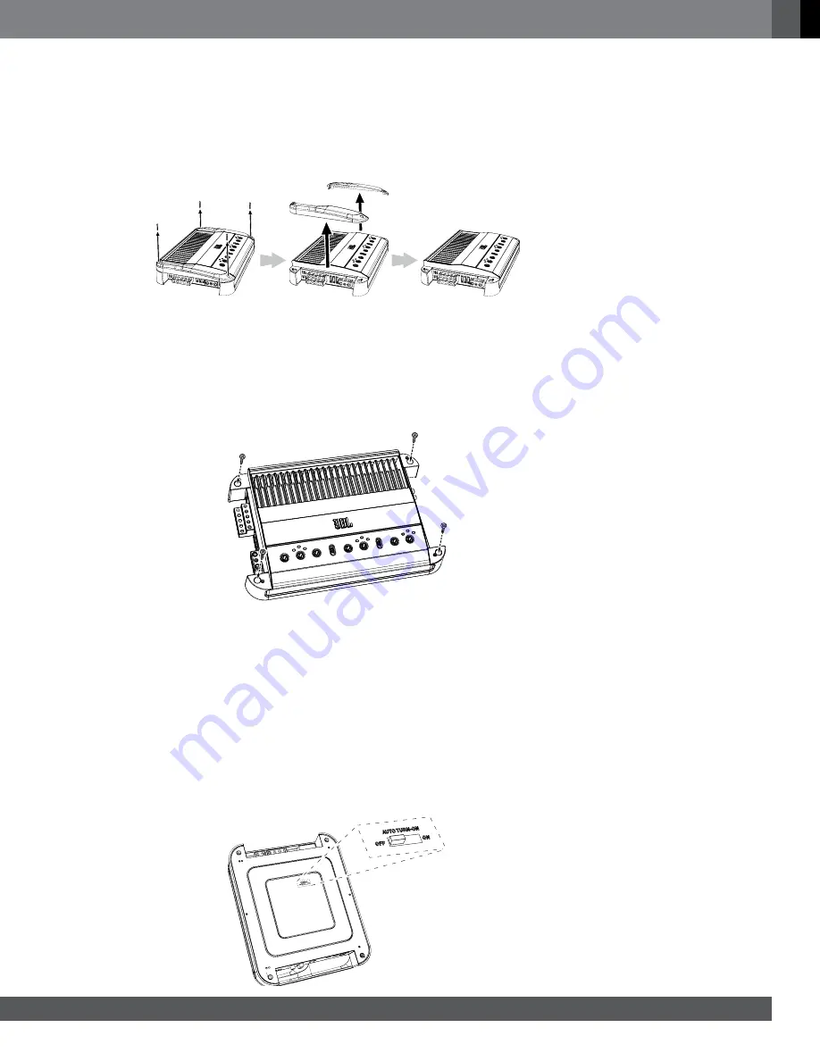
Before mounting the amplifier you must remove the two end caps to expose the mounting holes and the connections. 

Using a Phillips screwdriver, remove the attachment screws and then the end caps, as shown in the illustration. Put 

the screws in a safe place, so you can use them to reattach the end caps after you have made all the connections to 

the amplifier.

nOte:

 Before you permanently mount the amplifier, read 

Auto Turn-On Switch,

 below, to determine the setting of the 

switch, which is located on the amplifier’s bottom panel.

1. Select a suitable mounting location as described above.
2. Using the amplifier as a template, mark the locations of the mounting holes on the mounting surface.
3. Drill pilot holes in the mounting surface.
4.  Attach the amplifier to the mounting surface with four appropriate mounting screws of your own choice. We 

suggest using #8 Phillips-head sheet metal screws. Make sure the amplifier is mounted securely.

cOnnecTiOns

impOrtant: 

Disconnect the vehicle’s negative (–) battery terminal before beginning the installation.

If you have not already done so, remove the two end caps that cover the amplifier’s connectors as explained in 

Mounting the Amplifier,

 above. This will provide easier access to all of the amplifier’s connectors.

autO turn-On sWitch

No remote turn-on connection is necessary because GTO amplifiers include signal-sensing turn-on, which will turn 

the amplifier on when it receives an audio signal at any of its input connectors. The amplifier will automatically turn off 

approximately five minutes after the input signal ceases. 

If your audio system’s source unit includes a remote turn-on wire and you would prefer to use it, the amplifier 

will sense that you’ve used a remote turn-on wire and that connection will override the signal-sensing turn-on. If 

necessary, you can defeat the signal-sensing turn-on circuit by moving the Auto Turn-On switch to the “Off” position.

Summary of Contents for GTO-504EZ

Page 1: ...Owner s Manual GTO 804EZ GTO 504EZ power amplifier...

Page 2: ...kipping ahead is OK but please don t skip Setup Procedure on page 8 So we can better serve you should you require warranty service please retain your original sales receipt and register your GTO 804EZ...

Page 3: ...nting surface with four appropriate mounting screws of your own choice We suggest using 8 Phillips head sheet metal screws Make sure the amplifier is mounted securely Connections IMPORTANT Disconnect...

Page 4: ...the connector s set screw insert the bare wire and tighten the set screw to secure the wire in the connector Loosen Screw Insert Wire Tighten Screw Ground Connection Connect a wire minimum 8AWG 8 4mm...

Page 5: ...shed routing and connecting this wire install the appropriate fuse in the holder you installed near the battery GTO 804EZ 50A fuse GTO 504EZ 40A fuse Speaker Connections Always connect the terminal on...

Page 6: ...or information about connecting the inputs for bridged operation Input Connections The GTO 804EZ and GTO 504EZ amplifiers have multiple input connectors with a routing switch that increases flexibilit...

Page 7: ...se a short circuit that can damage the source unit or the amplifier When you re finished plug the adapter into the appropriate input connector on the amplifier For bridged operation Connect to the lef...

Page 8: ...t the Crossover Filter selector in the LP low pass position This will limit the amount of high frequency energy sent to the woofers or subwoofer If you have connected any other type of speaker to the...

Page 9: ...an amplifier connected to its output If this happens set the GTO amplifier s Input Level switch to the Hi2 position The Hi2 position includes a circuit designed to fool this type of factory system int...

Page 10: ...CAUTION Only use the Bass Boost control if you ve configured the rear channels to power a subwoofer Using the Bass Boost control with full range speakers can damage the speakers Power Protection LED P...

Page 11: ...ires Correct all short circuits before reconnecting the speakers to the amplifier If the amplifier does not turn on the Power Protect LED is still red contact your authorized JBL dealer for assistance...

Page 12: ...Fuse Replacement 25A x 2 Dimensions D x H x W 11 15 16 x 2 9 16 x 9 11 16 302mm x 66mm x 246mm Weight 8 4 lb 3 8kg GTO 504EZ Number of Channels 4 Power Output CEA 2006A 50W RMS x 4 channels at 4 ohms...

Page 13: ...ights reserved JBL is a trademark of HARMAN International Industries Incorporated registered in the United States and or other countries Features specifications and appearance are subject to change wi...

Reviews: