background image

9

www.jbl.com

E

ng

lis

h

• low-pass operation:

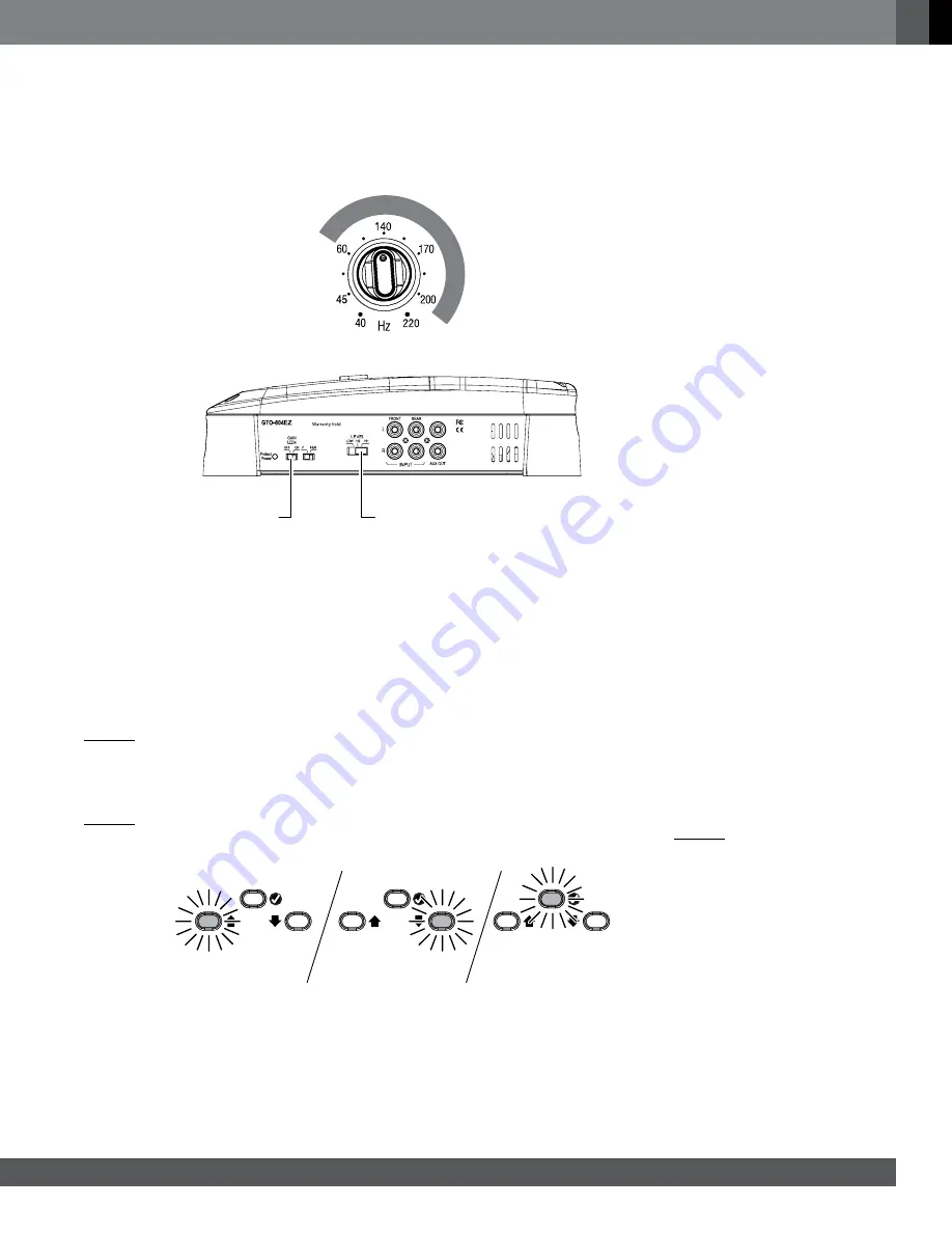
 The low-pass Crossover control setting you use for subwoofers will depend partly on the 

settings you use for the system’s high-pass channels (see above) and partly on the type and location of your 

system’s subwoofer. Start by setting the Crossover control to a frequency somewhat lower than the lowest 

setting you used on any of the high-pass channels. After listening to music on the system for a time, fine-tune the 

low-pass Crossover control setting to achieve a smooth transition from the subwoofer to the rest of the system’s 

speakers while avoiding a “hole,” where the sounds that occur between the subwoofer and other speakers seem 

to drop out. The illustration below shows the acceptable low-pass Crossover control frequency range.

set the gain

Gain LEDs 

Switch

Input Level 

Switch

Before beginning, make sure the Gain LEDs switch is set to the “On” position.

1. Initially set the amplifier Input Level switch to the “Hi1” position.


nOte:

 If you have connected the GTO-804EZ or GTO-504EZ amplifier to your factory audio system’s speaker 

outputs, the audio system may show a “speaker disconnected” message, or may fail to play with an amplifier 

connected to its output. If this happens, set the GTO amplifier’s Input Level switch to the “Hi2” position. The “Hi2” 

position includes a circuit designed to fool this type of factory system into “seeing” a speaker connected to its output.

2. Turn all amplifier Gain controls to the “Min” setting.
3. Play the supplied setup CD through the vehicle’s audio system.
4. Set the audio system head unit’s volume to maximum (all the way up).
5. SLOWLY advance the Gain control setting. The Gain Indicator LEDs will light up:


• Yellow LED = Gain is too low


• Green LED = Gain is OK


• Red LED = Gain is too high

6.  SLOWLY advance the Gain control so that the green Gain Indicator LED lights up. If you overshoot and the red 

LED lights up, turn the Gain control down so that the yellow LED lights up and advance the Gain control SLOWLY 

until the green LED lights up.

Gain too low 

(increase gain)

Gain OK

Gain too high 

(decrease gain)


nOte:

 If you advance the Gain control all the way and the yellow LED is still lit up, turn the Gain control to “Min,” 

switch the Input Level switch to the “Low” position and repeat Step 6.

7.  Repeat Steps 5 and 6 for all of the amplifier channels. When all Gain Indicator LEDs are lit green, the GTO 

amplifier gain setup is complete. 


 nOte: 

Set the amplifier’s Gain LEDs switch to the “Off” position to prevent the red LEDs from lighting up 

continually during normal operation.

Summary of Contents for GTO-504EZ

Page 1: ...Owner s Manual GTO 804EZ GTO 504EZ power amplifier...

Page 2: ...kipping ahead is OK but please don t skip Setup Procedure on page 8 So we can better serve you should you require warranty service please retain your original sales receipt and register your GTO 804EZ...

Page 3: ...nting surface with four appropriate mounting screws of your own choice We suggest using 8 Phillips head sheet metal screws Make sure the amplifier is mounted securely Connections IMPORTANT Disconnect...

Page 4: ...the connector s set screw insert the bare wire and tighten the set screw to secure the wire in the connector Loosen Screw Insert Wire Tighten Screw Ground Connection Connect a wire minimum 8AWG 8 4mm...

Page 5: ...shed routing and connecting this wire install the appropriate fuse in the holder you installed near the battery GTO 804EZ 50A fuse GTO 504EZ 40A fuse Speaker Connections Always connect the terminal on...

Page 6: ...or information about connecting the inputs for bridged operation Input Connections The GTO 804EZ and GTO 504EZ amplifiers have multiple input connectors with a routing switch that increases flexibilit...

Page 7: ...se a short circuit that can damage the source unit or the amplifier When you re finished plug the adapter into the appropriate input connector on the amplifier For bridged operation Connect to the lef...

Page 8: ...t the Crossover Filter selector in the LP low pass position This will limit the amount of high frequency energy sent to the woofers or subwoofer If you have connected any other type of speaker to the...

Page 9: ...an amplifier connected to its output If this happens set the GTO amplifier s Input Level switch to the Hi2 position The Hi2 position includes a circuit designed to fool this type of factory system int...

Page 10: ...CAUTION Only use the Bass Boost control if you ve configured the rear channels to power a subwoofer Using the Bass Boost control with full range speakers can damage the speakers Power Protection LED P...

Page 11: ...ires Correct all short circuits before reconnecting the speakers to the amplifier If the amplifier does not turn on the Power Protect LED is still red contact your authorized JBL dealer for assistance...

Page 12: ...Fuse Replacement 25A x 2 Dimensions D x H x W 11 15 16 x 2 9 16 x 9 11 16 302mm x 66mm x 246mm Weight 8 4 lb 3 8kg GTO 504EZ Number of Channels 4 Power Output CEA 2006A 50W RMS x 4 channels at 4 ohms...

Page 13: ...ights reserved JBL is a trademark of HARMAN International Industries Incorporated registered in the United States and or other countries Features specifications and appearance are subject to change wi...

Reviews: