background image

Additional System
Configurations for Add-On 
or Upgrade

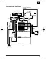
The features and capabilities of the
GTS100 provide tremendous system
design flexibility. The diagrams on the
following pages illustrate some of the
system possibilities. They are in order
of increasing complexity, showing the
way a system may be upgraded in 
logical steps. Although the systems are
shown using speaker-level connection
from the head-unit, they may be built
using any combination of speaker or
preamp level inputs, depending on the
capability of your head unit. (See 
pages 25-26.)

24

ence as a result of its switch-mode
operation. Although this is internally 
filtered and shielded by the GTS100
chassis, some unusually sensitive
installations may pick up switching
noise, especially when listening to weak
AM radio stations. If this unusual situa-
tion occurs, one of the following installa-
tion corrections will typically eliminate
the problem. 1) Relocate the amplifier
to a position farther away from the radio
or radio antenna. 2) Move the electrical
ground of the head unit and/or amp to a
different point on the vehicle’s chassis.
3) Keep the amplifier power supply
wiring away from the radio or antenna
wiring. 4) Wrap the +12 volt power sup-
ply wires for the radio/tape deck with
metallized shielding tape or ground
braid and ground the tape to the chas-
sis of the vehicle.

Maintenance

The GTS100 does not require any regu-
lar maintenance. Periodically checking
the main power supply and grounding
points and terminal connections is
advisable. Be sure the connections are
solid and corrosion-free. Loose or cor-
roded connections can cause annoying
intermittent noise or unusual opera-
tional problems. Do not allow dust to
accumulate on the amplifier heat sinks.
It will reduce the amplifier’s ability to
dissipate heat. Occasional vacuum
cleaning will prevent dust accumulation.

JBL 1394 Manual  7/17/98 11:49 AM  Page 24

Summary of Contents for GTS100

Page 1: ...G T S 1 0 0 GTS100 2 1CHANNELAUTOMOTIVEPOWERAMPLIFIER OWNER SMANUAL...

Page 2: ...tors 10 Mounting Instructions 12 Wiring 12 Power Supply Connections 14 Audio Input Connections 15 Speaker Connections 17 Operation 20 Solving Noise Problems 21 Maintenance 24 Additional System Configu...

Page 3: ...source or combined with a CD changer which includes volume control capability simultaneously connected directly to the amplifier 3 By providing this two unit direct connec tion Universal Interface ci...

Page 4: ...rmance potential Skill with tools an understanding of basic electronics and experience with car stereo installation are needed to properly install these amplifiers If you feel you do not have the nece...

Page 5: ...Recommended for experienced professional installers only 1 Disconnect the negative cable from the battery Note If the vehicle s radio features a code type security system make certain you know the cod...

Page 6: ...ms will likely cause overheating If monaural operation is desired and two 4 ohm speakers are used it is best to connect each speaker to an individual amplifier channel and use the L R mode on the inpu...

Page 7: ...ge to match with the accepted nor mal voltages and impedances used by virtually all car audio components With very few exceptions the GTS100 will match correctly to any equipment you already have 2 or...

Page 8: ...G T S 1 0 0 Speaker Level Input L R R L 2 or 4 Ohm Full Range Speakers L R Preamp Output Preamp Input 4 Ohm Subwoofer GTS100 B GTS100 A Application 4 Bi amplified System Using Preamp Output Capabilit...

Page 9: ...em once it is installed Before cutting or drilling any holes in the vehicle inspect the area carefully to be sure there are no electrical wires hydraulic brake lines fuel lines or fuel tanks that may...

Page 10: ...output Set switch to In for normal line level input operation Set the switch to Out to use the line level connector for line level outputs to drive other ampli fiers or signal processors when using t...

Page 11: ...lter on the amplifier for subwoofer use Set the switch to High to activate the 100Hz high pass filter for use with satellite speakers Note that the filter does not affect the line level outputs on the...

Page 12: ...r performance and long term reliability Using the proper type of wire is very important If a spe cific type of wire should be used for a certain application it will be noted All wiring connections sho...

Page 13: ...or Ground Power Supply Blue Blue White Remote On Off Remote Antenna Black Power Ground Red Main 12V Yellow Back Up Power Speakers Fuse Fuse Fuse Cassette Receiver Power Supply Wires POWER G T S 1 0 0M...

Page 14: ...rewall or other metal panel Ground Wire Black Proper grounding is extremely impor tant It has a significant effect on the overall performance and noise level of the system The ground wire must be soli...

Page 15: ...when a tape is played In such cases connect the remote turn on wire to an unused accessory terminal in the fuse block or any other 12 volt source that is turned 15 on and off with the vehicle s igniti...

Page 16: ...ode for the speaker level input harness is as follows NOTE The GTS100 has a built in 80Hz low pass subwoofer crossover and a 100Hz high pass satellite crossover Be sure the crossover switch is properl...

Page 17: ...ill acti vate the GTS100 when a powered source is used and the conventional remote connection of the preamp level source will activate the amp when it is used 17 Speaker Connections When connecting sp...

Page 18: ...lp you choose the correct values for your par ticular components The input mode switch should be set to STEREO Please do not call JBL for this part we stock only the harness assemblies as supplied wit...

Page 19: ...a different desired frequency by using the following formulas A Satellite Subwoofer High Pass x 300 F New Capacitor Value 100 desired frequency in Hz Low Pass x 6 2mH New Inductor Value 100 desired f...

Page 20: ...ill turn on and off with the head unit or the vehicle s ignition switch When the amplifier is turned on there is a time delay of several seconds longer in cold 20 Operation Before operating the GTS100...

Page 21: ...es and their wiring High performance audio equip weather before the amplifier will pro duce sound This eliminates the chance of annoying noises produced by the radio or signal processors being ampli f...

Page 22: ...A of current Higher power units of this type are best connected with their ground 22 ment is more likely to pick up such noise than conventional equipment because it has wide frequency band width and...

Page 23: ...lators are also available Switching Noise The GTS100 has a highly developed switching power sup ply which generates some RF interfer wires connected directly to the chassis of the head unit The tricki...

Page 24: ...urs one of the following installa tion corrections will typically eliminate the problem 1 Relocate the amplifier to a position farther away from the radio or radio antenna 2 Move the electrical ground...

Page 25: ...n speakers This is an excellent way to upgrade a good stock system Next Step Add power to Front Full Range Speakers see system 3 L L R R G T S 1 0 0 L L R R GTS100 Front Outputs Rear Outputs Front Ful...

Page 26: ...0 GTS100 GTS100 Get more power and system control by adding a second GTS100 to power the main speakers and subwoofers individually Use the built in crossover to high pass the front speakers and low pa...

Page 27: ...nections If no fault is found consult your JBL dealer Remote on wire between the head unit and the GTS100 is disconnected or defective check for 12 volts between the GTS100 remote on wire and the grou...

Page 28: ...the GTS100 and there is no output the GTS100 may be defective Alternator whine through the audio Ground loops Follow the wiring system with the engine running suggestions in the section called Solvin...

Page 29: ...200mV 8V RMS 1V at center detent Preamp Output Sensitivity 2V Out for 4V Speaker Level Input Minimum Speaker Impedance Single Ended Non Bridged 2 Ohms Bridged 4 Ohms Built In Electronic Crossover 80Hz...

Page 30: ...JBL Consumer Products Inc 80 Crossways Park West Woodbury NY 11797 8500 Balboa Blvd Northridge CA 91329 800 336 4JBL Part No JBLGTS100OM A Harman International Company...

Reviews: